Video telephony dialing

a video telephony and dialing technology, applied in the field of video telephony, can solve the problems of inconvenient use, limited commercial development, and inability to readily access digital access facilities to consumers' homes, and achieve the effect of using a cable-television-based video telephony system

Inactive Publication Date: 2000-05-23
AMERICAN TELEPHONE & TELEGRAPH CO
View PDF5 Cites 18 Cited by
  • Summary
  • Abstract
  • Description
  • Claims
  • Application Information

AI Technical Summary

Benefits of technology

In accordance with the present invention, the usefulness of a cable-television-based video telephony system of the type just described is enhanced by administering the video telephone number for cable subscriber locations to be the same as the standard ten- (i.e., area code plus seven-) digit telephone number used for regular telephone calls directed to those locations. Thus the subscriber at an originating cable subscriber location will enter on the aforementioned NIU keypad the seven- or ten-digit telephone number associated with the conventional telephone set that is installed at the destination cable subscriber location. This is advantageous in that, apart from the fact that a cable-subscriber-originated video call, rather than a conventional voice-only call, is being made, the subscriber at an originating cable location is given the illusion that he / she is initiating a dial-up connection similar to any other dial-up connection that proceeds exclusively through the telephone network, such as a simple voice-only call. That is, since the video telephone call is initiated to the same telephone number that would have been used if this were a conventional voice call made to the desired destination subscriber location, it appears to the originating subscriber that all he / she has done is "dial up" the desired destination subscriber from what appears to be nothing more or less than a video-capable "extension" telephone within the originating location. Additionally, subscribers can "give out" a single telephone number to friends and other potential callers, not having to differentiate between "my voice number" and "my video number" but yet still being able to receive both kinds of calls directed to that same telephone number.

Problems solved by technology

However, due to the limited bandwidth of conventional telephone lines, and the consequent limitation on the amount of information that can be carried therethrough, commercial development has been limited to less-than-full-motion video presented on a small display.
However, at the present time, digital access facilities to consumer homes are not readily available.
However, these facilities are expensive, and thus are not accessible to the ordinary household.
Besides, it will be decades before most homes are provided with fiber access.

Method used


Image

  • Video telephony dialing
  • Video telephony dialing
  • Video telephony dialing

Examples


Embodiment Construction

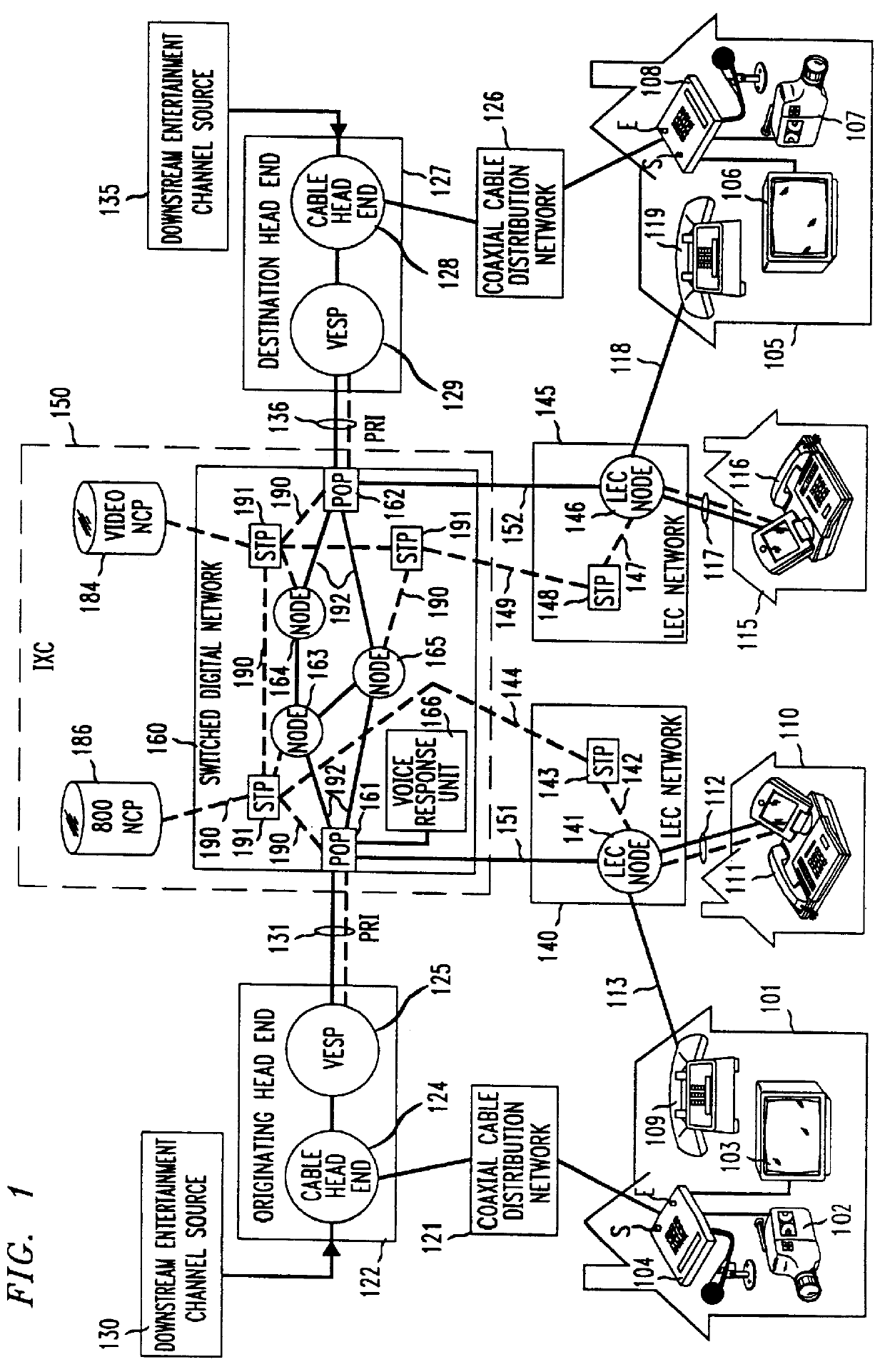
The block diagram of FIG. 1 shows a video telphony system similar to that disclosed in the above-cited Yu patent application. In particular, an originating cable subscriber location 101 is shown to be able to communicate to a selected destination cable subscriber location 105 in a video telephone call established via a switched digital telecommunications network 160, the latter being part of an interexchange carrier (IXC)

network 150. Cable subscriber locations 101 and 105 are illustratively private residences, although they need not be. The gateways to network 160 are point of presence (POP) locations 161, 162, which are described in more detail below.

Originating and destination cable subscriber locations 101 and 105 are connected to POPs 161 and 162, respectively, via connections which include respective connections through cable television distribution networks 121 and 126. In particular, audio and video communication between a network interface unit (NIU) 104 (described in more d...


PUM


Abstract

In a video telephony system, a coaxial cable network, which is preferably a part of an existing cable television system, provides a local link for the transmission of the video telephone signals between each originating and destination location and a respective "head end" located on the cable company premises. Each of the head ends is connected to a "point of presence" of a telephone interexchange carrier so that a connection between pairs of head ends, and thus between a pair of video telephone locations, can be made via a switched digital network maintained by the carrier. Certain of originating and destination locations comprise a standard television set, serving as the audio / video display, and a consumer-type camera or camcorder, serving as the audio / video source. Others of the originating and destination locations comprise ISDN video telephones which are connected to the various points of presence of the interexchange carrier via local exchange carrier telephone networks. The video telephone numbers for cable subscriber locations are administered to be the same as the standard ten- (i.e., area code plus seven-) digit telephone numbers used for regular telephone calls directed to those locations.

Description

FIELD OF THE INVENTIONThis invention relates generally to video telephony and, more specifically, to bidirectional transmission of voice and picture information among a large number of geographically distributed users.BACKGROUND OF THE INVENTIONBecause two-way video communications can give individuals the ability to communicate graphical information and to see facial expressions and gestures that cannot be conveyed by audio alone, much emphasis has been placed on commercial development of such systems. Indeed, video telephones that work with analog telephone lines have been demonstrated. However, due to the limited bandwidth of conventional telephone lines, and the consequent limitation on the amount of information that can be carried therethrough, commercial development has been limited to less-than-full-motion video presented on a small display.In order to overcome the bandwidth limitation associated with video telephony transmitted over the analog telephone lines, video telephone...

Claims


Application Information

Patent Timeline
Patent Type & Authority Patents(United States)
IPC IPC(8): H04M11/00H04N7/14H04Q11/04H04L29/12H04L12/28H04M3/42H04M3/00H04M3/56
CPCH04L12/2801H04L29/12018H04L61/10H04M11/00H04N7/147H04N7/148H04Q11/0428H04Q11/0435H04L29/12009H04Q2213/13337H04Q2213/13097H04Q2213/13103H04Q2213/13176H04Q2213/13209H04Q2213/13248H04Q2213/13332H04L61/00
Inventor PAPANICOLAOU, ANDREAS CONSTANTINEYU, CHENG D.
Owner AMERICAN TELEPHONE & TELEGRAPH CO
Why Eureka
Try Eureka