Exoskeleton and method of providing an assistive torque to an arm of a wearer

a technology of assistive torque and exoskeleton, which is applied in the direction of computer control, program control, instruments, etc., can solve the problems of increasing the muscular effort required, rapid fatigue, and high static load on the body, so as to reduce user fatigue, improve the strength of wearers, and reduce the weight borne by wearers

Active Publication Date: 2018-08-28
EKSO BIONICS
View PDF60 Cites 11 Cited by
  • Summary
  • Abstract
  • Description
  • Claims
  • Application Information

AI Technical Summary

Benefits of technology

[0005]The exoskeletons of the present invention act to improve a wearer's stamina by transferring the weight of the wearer's arms, as well as a tool or load, through the exoskeleton structure, thereby decreasing the weight borne by the wearer. More specifically, an exoskeleton vest provides arm supports that support both the weight of the wearer's physical arms as well as the weight of a tool, reducing user fatigue and providing tool-holding assistance. Weight is transferred from the wearer's hands and arms through the arm supports and vest spine to a hip belt. The wearer guides the arm supports' vertical motion to move the arm supports and any held tools, with the exoskeleton aiding the wearer by supporting the weight of the wearer's arms and the tools. This support is especially beneficial when the wearer is performing work at or above eye level or performing repetitive tasks for prolonged periods of time. The design of the exoskeleton vest structure, and in particular the structure of the arm supports, plays a significant role in the usefulness of the exoskeleton to the wearer in workplace applications.
[0006]The exoskeleton vest supports and / or augments the strength of a wearer's arms, allowing the wearer to more easily manipulate and use his or her arms to perform any of a variety of repetitive work tasks without the strain and fatigue that would be present without the exoskeleton vest's support structure. The exoskeleton vest's arm supports follow the wearer's arms and provide an assistive torque that approximately balances the weight of the wearer's arms and any tools held by the wearer. In accordance with one aspect of the invention, the assistive torque goes to zero as the wearer's arms are lowered to the end of travel, thereby enabling the wearer to place the device into a non-assistive mode so that he or she can remove his or her arms from the arm supports without device recoil or other movement. In another aspect, the exoskeleton vest is adjustable for body size and personal ergonomic considerations. This adjustability means that the device's single size fits most people. In an alternative embodiment, rather than being provided as part of an exoskeleton vest, the arm supports are attached to a physical object such as a chair or table. In this type of arrangement, the arm supports still support a person's arms and provide a corresponding efficacy that they offer to a wearer of an exoskeleton vest.
[0010]In still another embodiment, the exoskeleton further includes a mounting bar, a third link and a detent rail. The mounting bar is directly coupled to the spinal column. The first link includes a first end directly coupled to the mounting bar and a second end directly coupled to a first end of the second link. The second link includes a second end directly coupled to a first end of the third link, and the third link includes a second end directly coupled to the arm support assembly. The detent rail is directly coupled to the arm support assembly and the cuff. The mounting bar is configured to allow the first link to be located at a plurality of different positions relative to the spinal column, thereby enabling the exoskeleton to be adjusted to fit different wearers. The detent rail is configured to allow the cuff to be located at a plurality of different positions relative to the arm support assembly, thereby further enabling the exoskeleton to be adjusted to fit different wearers. The third link is configured to pivot in a transverse plane about a third vertical axis, thereby further allowing the arm support assembly to move relative to the spinal column. The first link pivots relative to the mounting bar about the first vertical axis. The first and second links pivot relative to one another about the second vertical axis. The second and third links pivot relative to one another about the third vertical axis. The third link and the arm support assembly pivot relative to one another about the horizontal axis.
[0011]In a still further embodiment, the exoskeleton includes a mounting bar. The arm support assembly, the first link, the second link and the cuff form at least a portion of a support arm. The mounting bar connects the support arm to the spinal column. The mounting bar is configured to allow the support arm to be located at a plurality of different positions relative to the spinal column, thereby enabling the exoskeleton to be adjusted to fit different wearers. The exoskeleton also includes a detent rail. The detent rail connects the cuff to the arm support assembly. The detent rail is configured to allow the cuff to be located at a plurality of different positions relative to the arm support assembly, thereby further enabling the exoskeleton to be adjusted to fit different wearers.

Problems solved by technology

Holding a static posture places very high static loads on the body, resulting in rapid fatigue.
Static postures add to the muscular effort required to do tasks and the lack of motion impedes blood flow.
Similarly, the overuse of muscles and tendons in the upper body, including but not limited to the hands, arms, shoulders, back and neck, can result in fatigue and repetitive strain injuries (RSIs).

Method used


Image

  • Exoskeleton and method of providing an assistive torque to an arm of a wearer
  • Exoskeleton and method of providing an assistive torque to an arm of a wearer
  • Exoskeleton and method of providing an assistive torque to an arm of a wearer

Examples


Embodiment Construction

[0023]Detailed embodiments of the present invention are disclosed herein. However, it is to be understood that the disclosed embodiments are merely exemplary of the invention that may be embodied in various and alternative forms. The figures are not necessarily to scale, and some features may be exaggerated or minimized to show details of particular components. Therefore, specific structural and functional details disclosed herein are not to be interpreted as limiting, but merely as a representative basis for teaching one skilled in the art to employ the present invention.

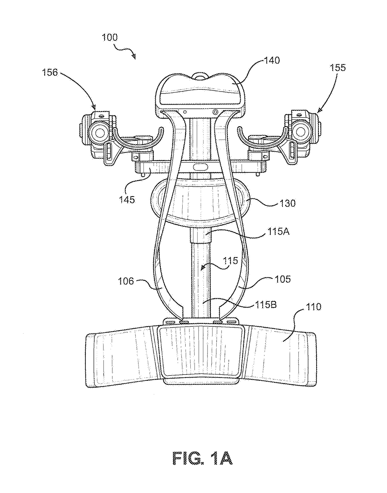
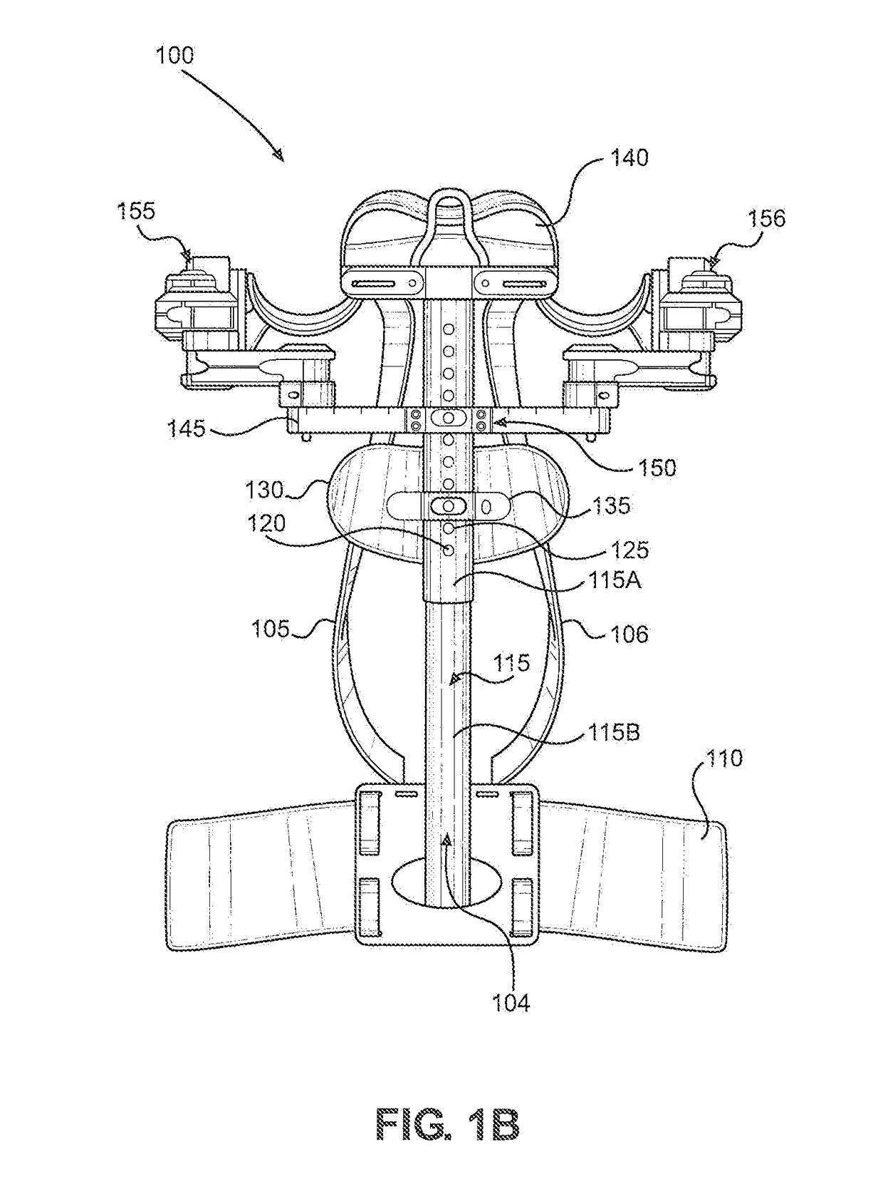
[0024]With initial reference to FIGS. 1A and 1B, there is shown an exoskeleton 100 in accordance with the present invention. Figure 1A provides a front view of exoskeleton 100, while FIG. 1B provides a rear view. In the embodiment shown, exoskeleton 100 takes the form of a vest, which is wearable by a person and enables the wearer to perform work while his or her arms are fully supported by exoskeleton 100. Among o...


PUM


Abstract

An exoskeleton includes a first link that pivots in a transverse plane about a first vertical axis and a second link that pivots in a transverse plane about a second vertical axis. The second link is coupled to the first link. An arm support assembly is coupled to the second link and pivots about a horizontal axis. The arm support assembly includes a spring that generates an assistive torque that counteracts gravity. The arm support assembly provides the assistive torque to an arm of a wearer to support the arm of the wearer. The arm support assembly further includes a cam profile and a cam follower. Contact between the spring, cam follower and cam profile determines an amount of the assistive force provided by the arm support assembly. A cuff is coupled to the arm support assembly and the arm of the wearer.

Description

CROSS REFERENCE TO RELATED APPLICATIONS[0001]This application claims the benefit of U.S. Provisional Patent Application Ser. No. 62 / 270,996, which was filed on Dec. 22, 2015 and titled “Human Exoskeleton Vest”. The entire content of this application is incorporated by reference.FIELD OF THE INVENTION[0002]The present invention relates to devices that augment a wearer's capacity, stamina, and strength when working with arms outstretched in a static position. The devices also offer the same utility to wearers that are carrying out repeated arm and shoulder movements during the performance of work. The devices increase performance and aid in the prevention of injury during the execution of certain, often repetitive, tasks. More particularly, the present invention relates to wearable devices with arm supports suitable for use by a person engaged in assembly line work or other activities that require the person to use his or her arms to hold tools and perform manual tasks for long period...

Claims


Application Information

Patent Timeline
Patent Type & Authority Patents(United States)
IPC IPC(8): G05B15/00B25J9/14B25J9/10B25J9/00G05B19/00
CPCB25J9/0006B25J9/106B25J9/14B25J9/109Y10S901/02A61H1/0281A61H2201/165B25J9/042B25J9/1633B25J18/04
Inventor ANGOLD, RUSSLUBIN, JAMESSOLANO, MARIOPARETICH, CHRISMASTALER, TOM
Owner EKSO BIONICS
Why Eureka
Try Eureka