
Current collector for double electric layer electrochemical capacitors and method of manufacture thereof
a current collector and electrochemical capacitor technology, applied in the field of electrochemical supercapacitors, can solve the problems of low stability, low specific resistance of thin oxidation layer, low operating stability, etc., and achieve high over-voltage of hydrogen and oxygen gassing, low cost, and convenient availability
Patent Information
- Authority / Receiving Office
- US · United States
- Current Assignee / Owner
- Publication Date
- 2006-12-28
- Estimated Expiration
- Not applicable · inactive patent
Smart Images
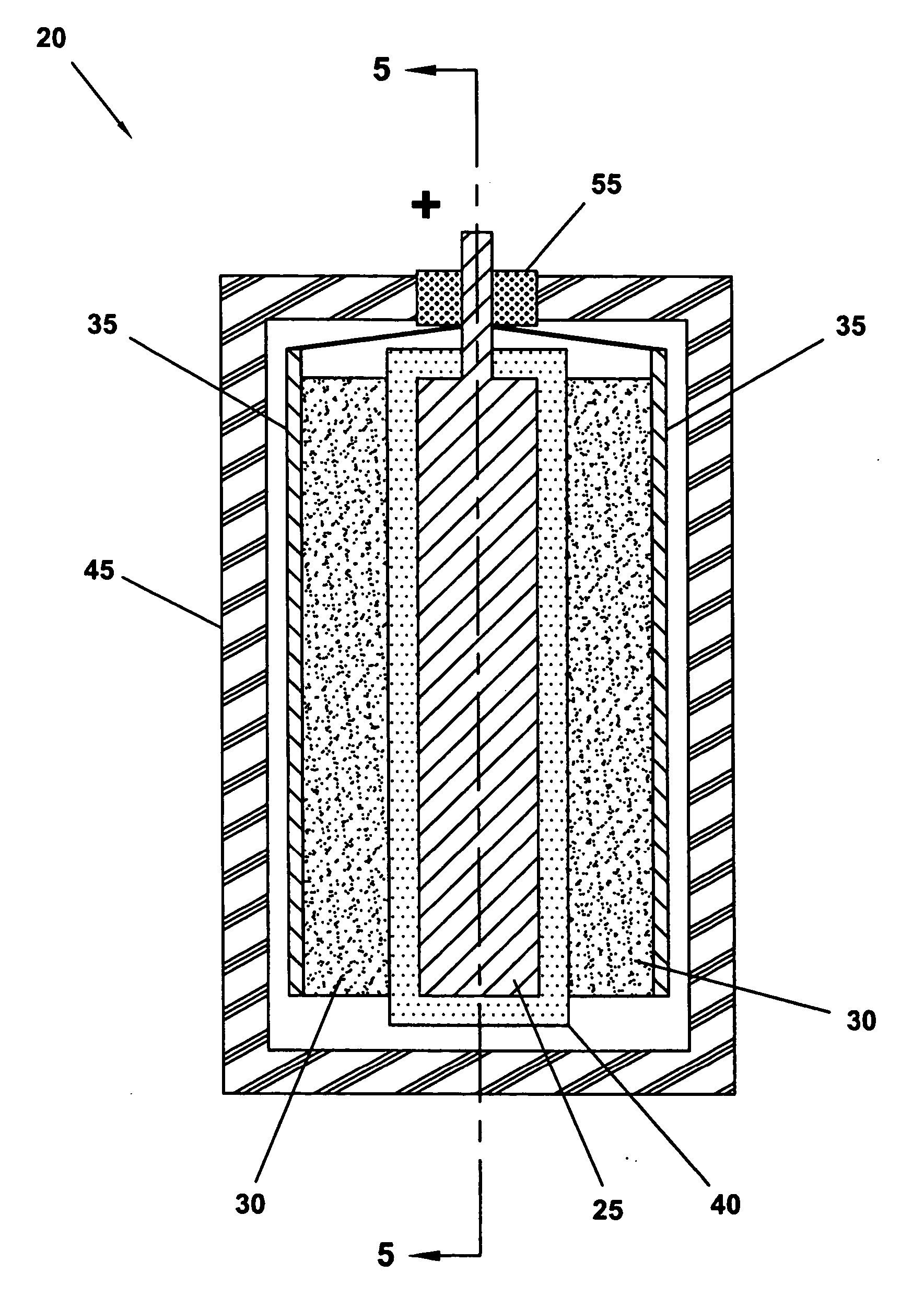
Figure 1 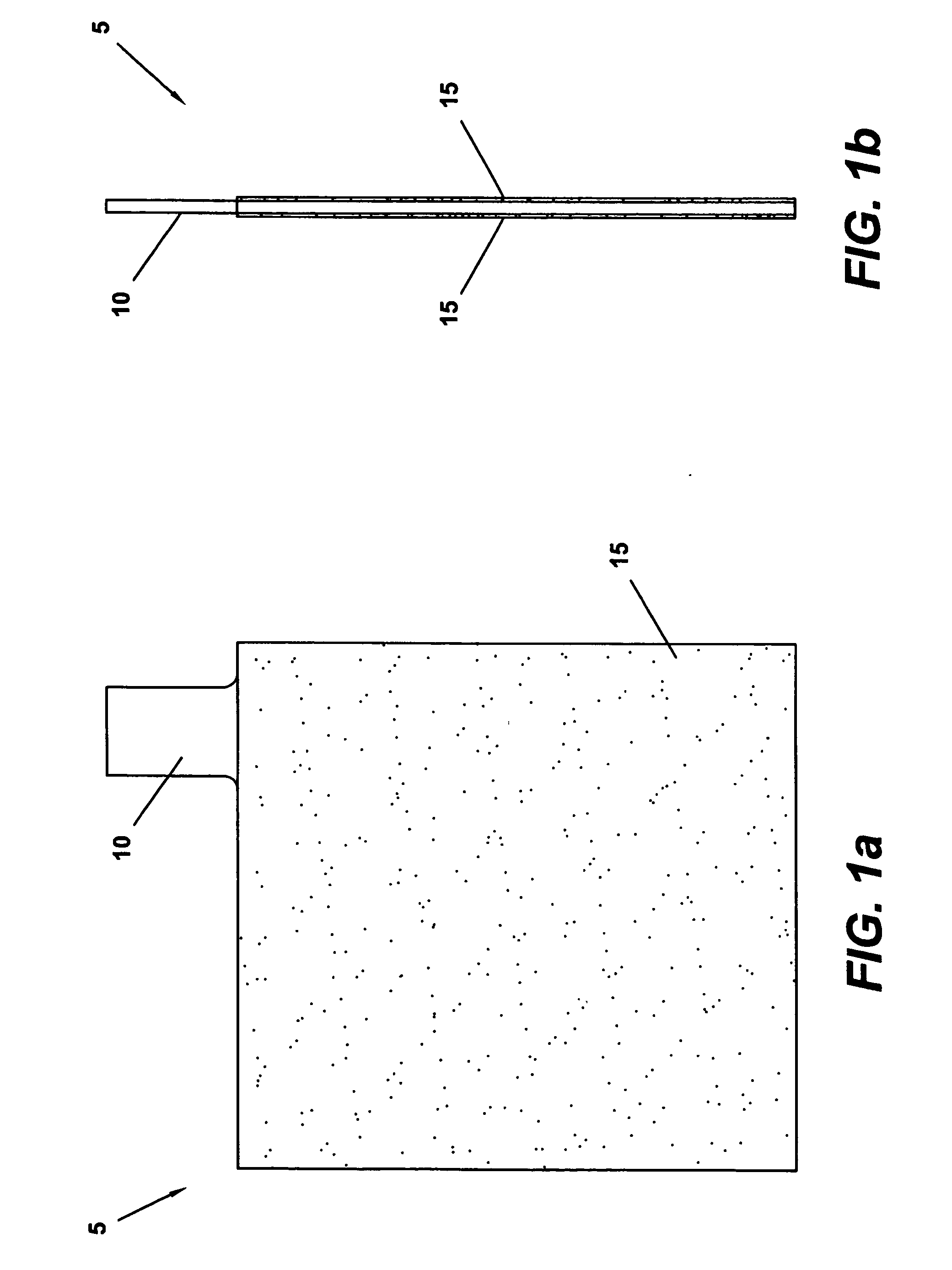
Figure 2 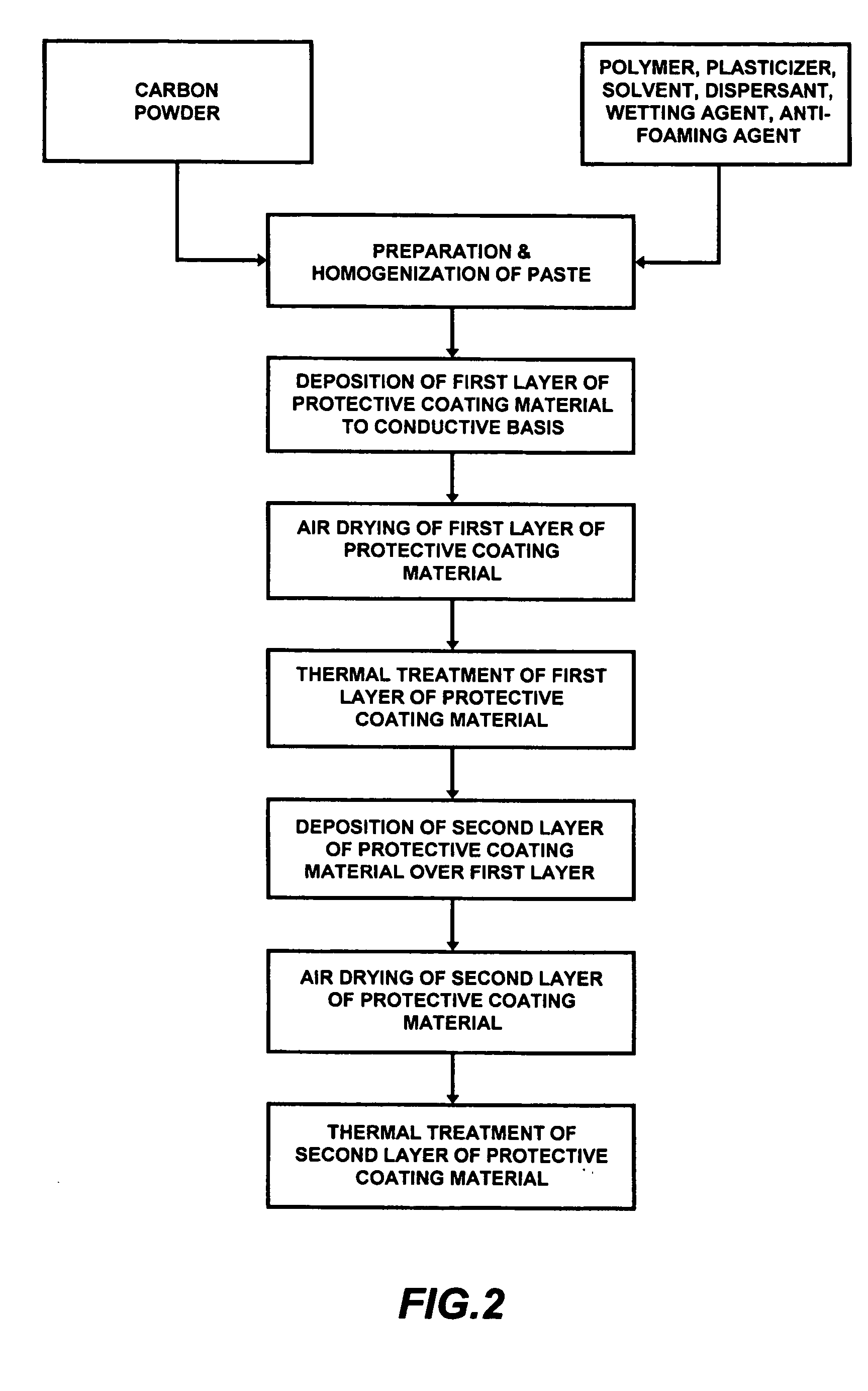
Figure 3
Abstract
Description
[0001] This application claims the benefit of PCT application Ser. No. PCT / RU05 / 000349, filed on Jun. 24, 2005.BACKGROUND OF THE INVENTION
[0002] The present invention is directed to the field of electrochemical capacitors, and particularly electrochemical supercapacitors. More specifically, the present invention is directed to a current collector for use in a double electric layer electrochemical supercapacitor electrode assembly.
[0003] There is an increasing focus on the use of capacitors as a means for storing electrical energy. These capacitors can efficiently store and redistribute a large amount of electrical energy. For example, such capacitors may be used: as a main power supply; as a back-up power supply; and for power quality assurance (e.g., to compensate for short-term power “surges”, “spikes”, and “skips” common to utility-supplied electric power). Such capacitors may also be used to provide load-leveling by storing an amount of electrical energy provided during off-pe...
Examples
example 1
[0048] An exemplary current collector was manufactured according to the technique described above. The current collector had conductive basis dimensions of approximately 135×72×0.2 (mm). A protective coating material was deposited to the conductive basis in two separate layers, such that the final protective layer thickness was approximately 50 μm. The conductive basis was manufactured from a lead alloy, namely an alloy comprised of approximately 97% lead and approximately 3% tin. The composition of the current collector protective coating paste was approximately 6.0 weight % carbon powder; 5.2 weight % perchlorovinyl polymer; 8.2 weight % plasticizer; 80 weight % solvent (acetone, n-butyl acetate, toluol); 0.3 weight % dispersant; 0.15 weight % wetting agent (surfactant); and 0.15 weight % antifoaming agent. After thermal treatment of the second of the two protective coating material layers, the composition of the protective layer was 30 weight % carbon powder; 45 weight % perchlor...
example 2
[0069] Another exemplary current collector was manufactured in a manner similar to that described above. The current collector again had conductive basis dimensions of approximately 135×72×0.2(mm). A protective coating material was deposited to the conductive basis in two separate layers, such that the final protective layer thickness was approximately 50 μm. The conductive basis was manufactured from a lead alloy, namely an alloy comprised of approximately 99% lead and approximately 1% tin. The composition of the current collector protective coating paste was approximately 4.0 weight % carbon powder; 9.7 weight % perchlorovinyl polymer; 6.0 weight % plasticizer; 80 weight % solvent (acetone, n-butyl acetate, toluol); 0.1 weight % dispersant; 0.1 weight % wetting agent (surfactant); and 0.1 weight % antifoaming agent. After thermal treatment of the second of the two protective coating material layers, the composition of the protective layer was 20 weight % carbon powder; 52 weight %...