
Choke device for an internal combustion engine intake system
Patent Information
- Authority / Receiving Office
- US · United States
- Current Assignee / Owner
- Publication Date
- 2007-07-19
- Estimated Expiration
- Not applicable · inactive patent
Smart Images
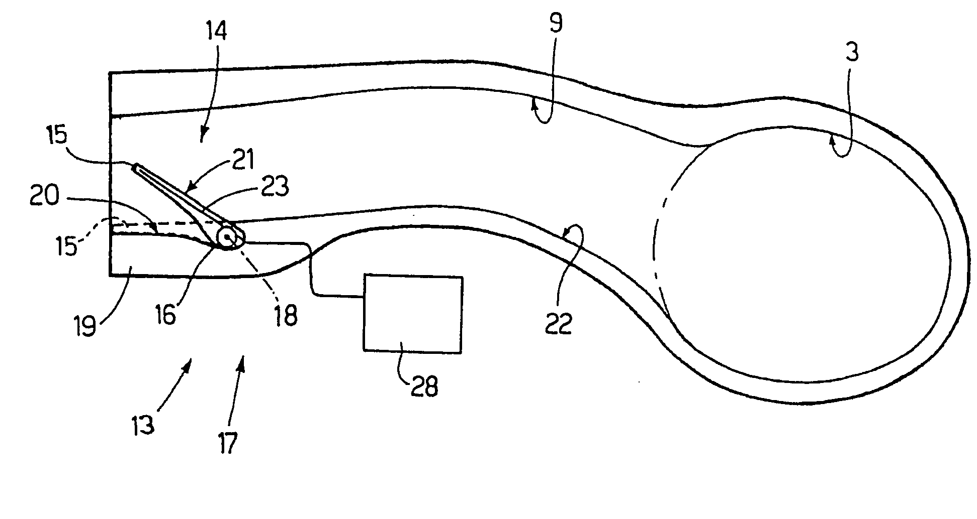
Figure 1 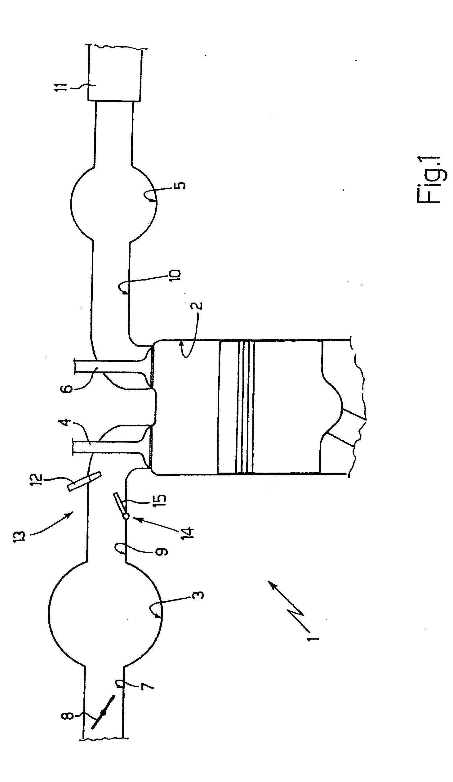
Figure 2 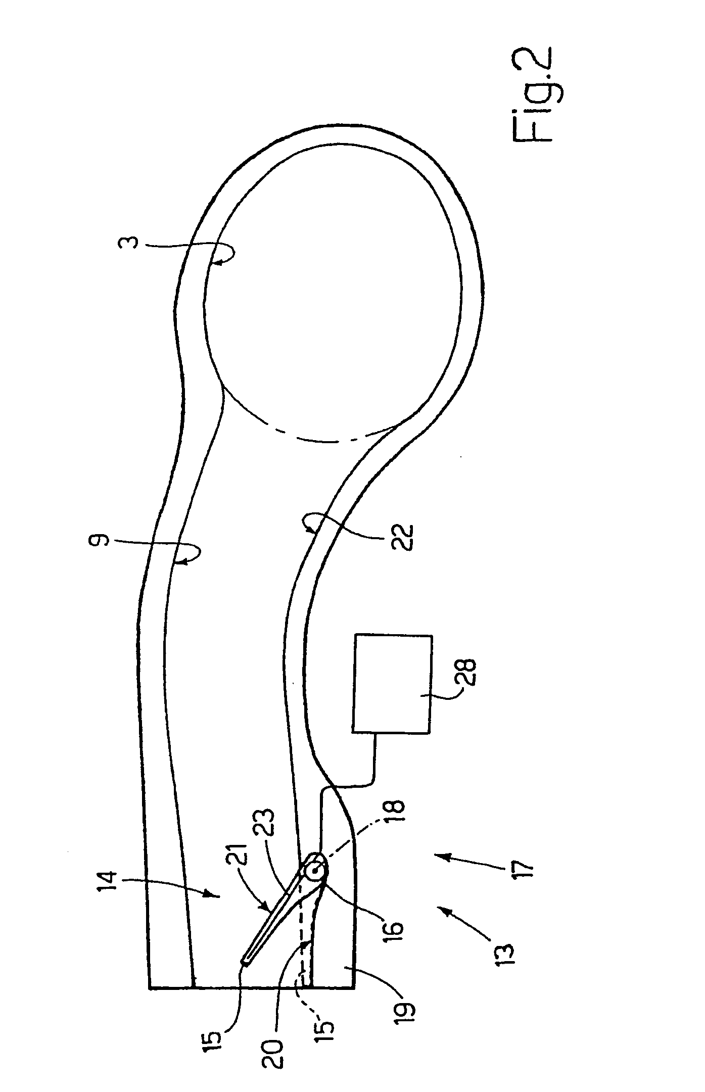
Figure 3
Abstract
Description
[0001] The present invention relates to a choke device for an internal combustion engine intake system. BACKGROUND OF THE INVENTION
[0002] An internal combustion engine has a number of cylinders, each connected to an intake manifold by at least one intake valve, and to an exhaust manifold by at least one exhaust valve. The intake manifold is supplied with fresh air (i.e. from outside) by a feed conduit fitted with a throttle valve, and is connected to the cylinders by respective intake conduits, each terminating at least one intake valve.
[0003] A choke device has recently been proposed to adjust the cross section of the intake conduits as a function of engine speed (i.e. drive shaft rotation speed). At low speed, the airflow section of the intake conduits is reduced to generate turbulence in the air intake and so improve mixing of the air and fuel in the cylinders, so that all the injected fuel is burnt, thus reducing combustion-generated pollutant emissions. At high speed, the air...
Examples
Embodiment Construction
[0013] Number 1 in FIG. 1 indicates as a whole an internal combustion engine having four cylinders 2 (only one shown in FIG. 1), each of which is connected to an intake manifold 3 by at least one intake valve 4, and to an exhaust manifold 5 by at least one exhaust valve 6.
[0014] Intake manifold 3 is supplied with fresh air (i.e. from outside) by a feed conduit 7 regulated by a throttle valve 8, and is connected to cylinders 2 by respective intake conduits 9 (only one shown in FIG. 1), each of which is regulated by the corresponding intake valve 4. Similarly, exhaust manifold 5 is connected to cylinders 2 by respective exhaust conduits 10 (only one shown in FIG. 1), each of which is regulated by the corresponding exhaust valve 6; and an exhaust pipe 11 extends from exhaust manifold 5 and terminates with a known muffler (not shown) to expel combustion gases into the atmosphere.
[0015] In the embodiment shown, fuel (e.g. petrol, diesel fuel, methane, LPG, . . . ) is injected into each...