

Helical spring and suspension gear
A suspension device and vehicle technology, which is applied in the field of coil springs and vehicle suspension devices, and can solve the problems of impossibility to apply to occasions with limited installation space, low-cost manufacturing, large buckling displacement, etc.
- Summary
- Abstract
- Description
- Claims
- Application Information
AI Technical Summary
Problems solved by technology
Method used
Image

Examples
Embodiment Construction
[0038] Embodiments applicable to the present invention will be described in detail below with reference to the accompanying drawings.
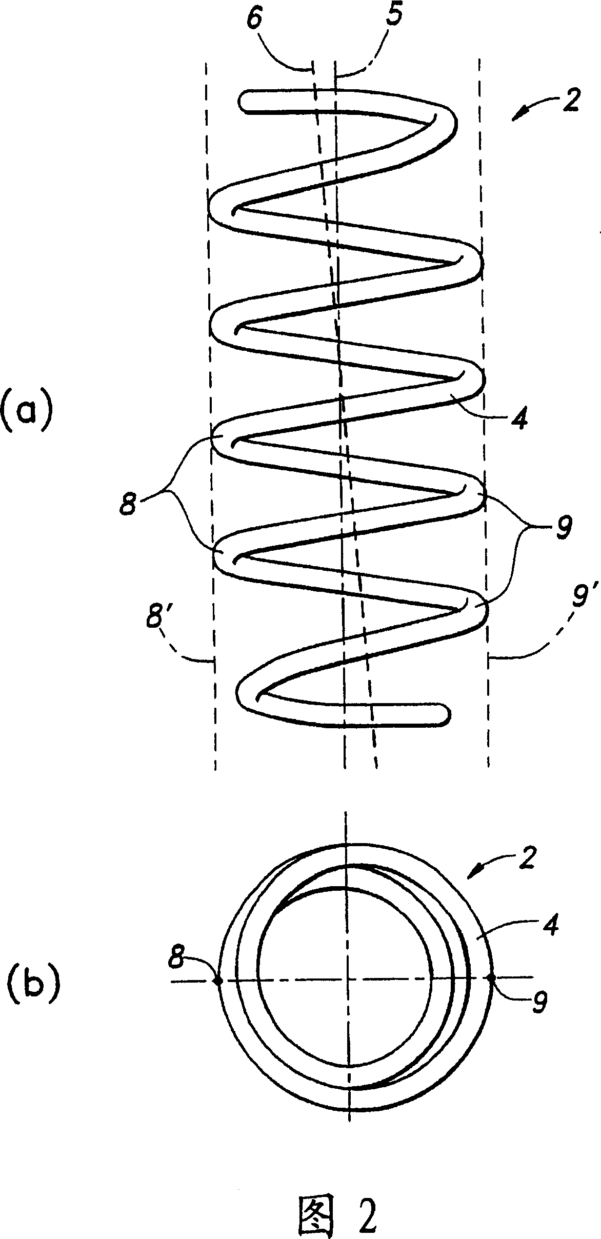
[0039] Figures 2a and 2b show a compression helical spring 2 with a mounted retaining ring portion in a prior art form. In general, a compression coil spring is formed by winding a helical wire 4 around a central axis 5 . Due to the limited number of turns, it cannot be completely symmetrical around the central axis 5 , so the load axis 6 is slightly inclined relative to the central axis 5 . The load axis 6 can be regarded as the direction of the reaction force generated on the spring 2 when a load is applied in the direction of the central axis 5 .
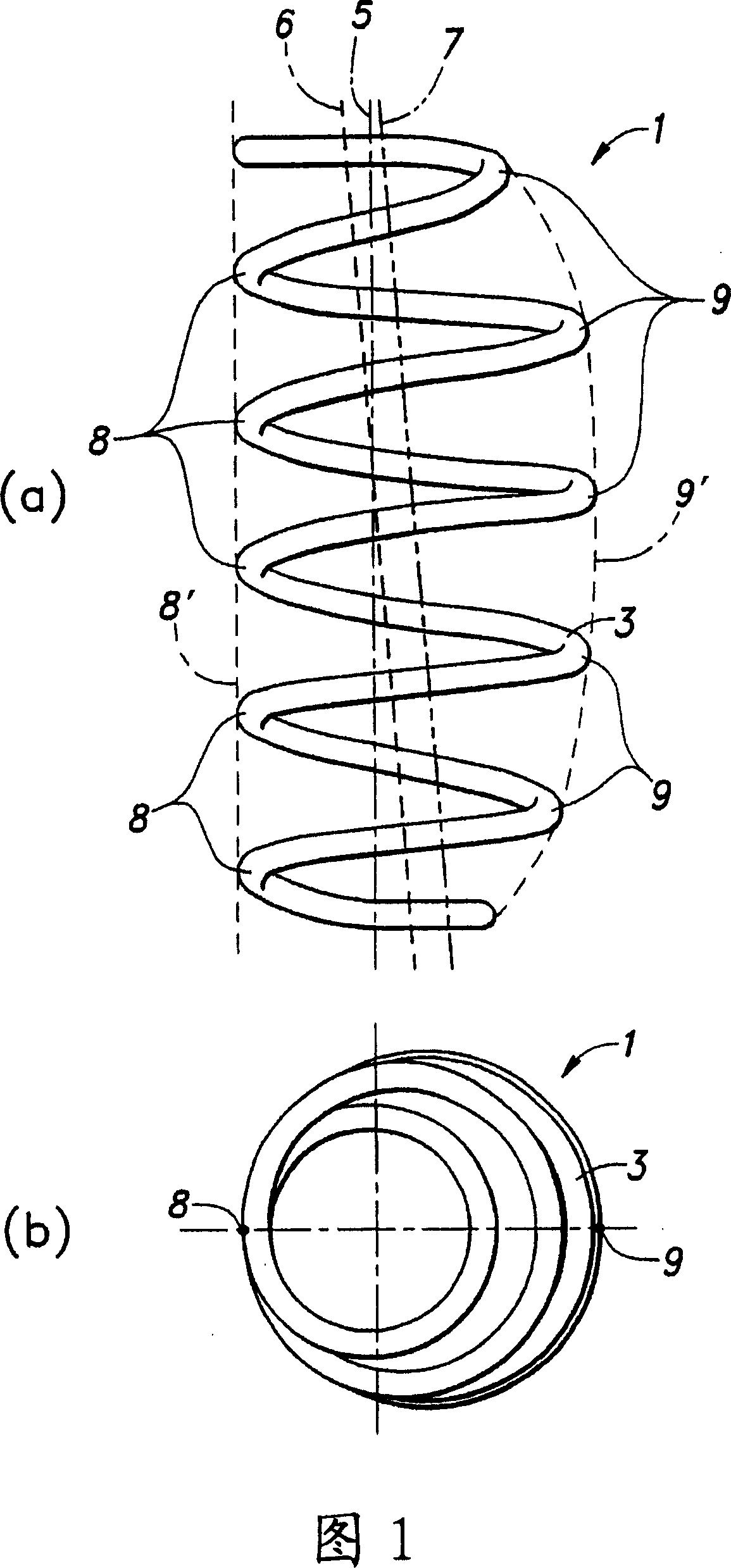
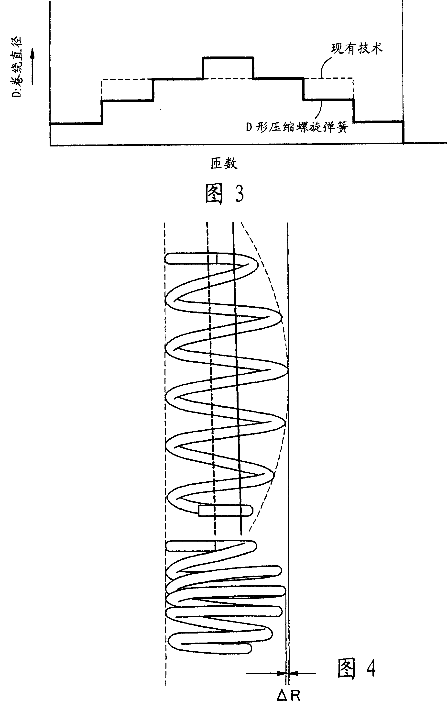
[0040] Figures 1a and 1b show a D-shaped compression coil spring 1 according to the present invention. One side position 8 is used as the reference position for changing the winding diameter, and the straight line 8' connecting one side position 8 is roughly parallel to the central axis (the ins...
PUM
 Abstract
Description
Claims
Application Information