
Column control circuit of organic electroluminous display screen
A display screen and luminescent technology, applied in the direction of electroluminescent light source, electric light source, light source, etc., to achieve the effects of improving transmission utilization, increasing display frame frequency, and reducing brightness loss
- Summary
- Abstract
- Description
- Claims
- Application Information
AI Technical Summary
Problems solved by technology
Method used
Image

Examples
Embodiment Construction
[0048] A preferred embodiment of the present invention is described in detail as follows in conjunction with accompanying drawing:
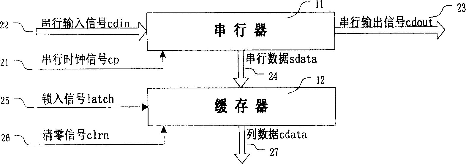
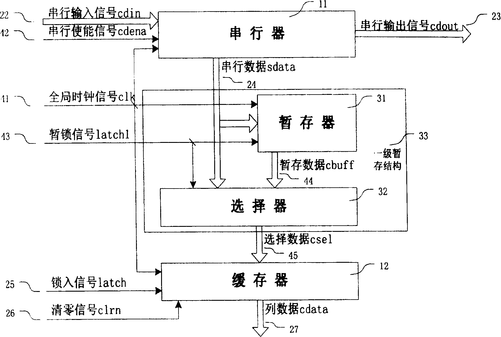
[0049] This embodiment is to figure 1 The lock-in signal latch(25) and zero-clearing signal clrn(26) in the traditional OLED column control circuit shown in the figure are changed to synchronous signals, and the serial clock signal cp(21) is changed to a global clock signal and renamed to clk(41) , add a serial enable signal cdena (42), when the signal is active high, allow the serial lock-in signal cdin (22), add a temporary register (31) and a selector (32), and add a temporary Lock signal latch1 (43), temporary register (31), selector (32) and temporary lock signal latch1 (43) constitute one-level temporary storage structure (33), as image 3 shown.
[0050] exist image 3 Among them, the serializer (11) is a multi-group multi-bit band enable register, and multiple registers share the same clock terminal to access the global clock signal cl...
PUM
 Abstract
Description
Claims
Application Information