
Camera

A technology of a camera device and a rotating head, which is applied to projection devices, printing devices, image communication and other directions, can solve problems such as inconvenience in use, and achieve the effects of convenient use, large shooting area and simple structure

Active Publication Date: 2009-02-04
VIMICRO ELECTRONICS CORP
View PDF6 Cites 0 Cited by
  • Summary
  • Abstract
  • Description
  • Claims
  • Application Information

AI Technical Summary

Problems solved by technology

However, since the pan-tilt device and the camera device are two devices, there are many inconveniences in use.

Method used


Image

  • Camera
  • Camera
  • Camera

Examples


Embodiment Construction

[0030] The present invention will be further described in detail below in conjunction with the accompanying drawings and specific embodiments.

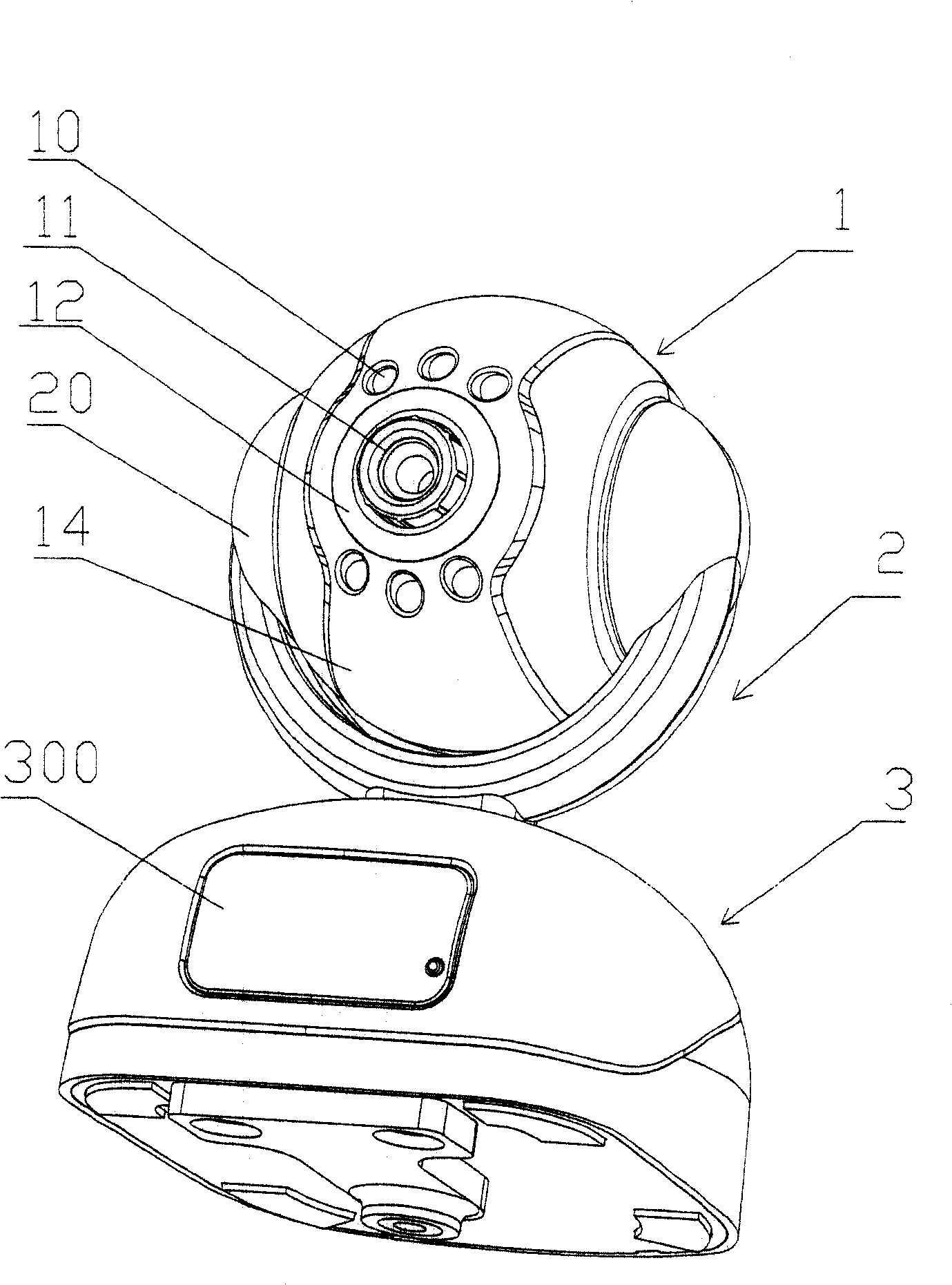
[0031] refer to figure 1 , an imaging device provided by the present invention is composed of a rotating head 1 , a bracket 2 and a base 3 . Wherein, the rotating head 1 is arranged on the upper part of the bracket 2 so as to rotate up and down, and the lower part of the bracket 2 is arranged on the base 3 so as to rotate left and right.

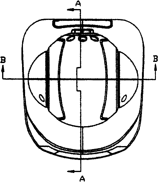
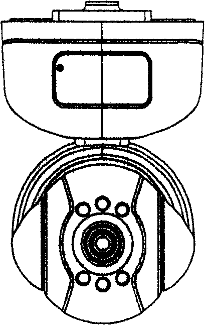
[0032] refer to figure 1 , image 3 , Figure 6 As shown in FIG. 11 , the rotary head 1 is assembled into a hollow sphere by the front shell 13 and the rear shell 17 , the front shell 13 is also provided with a front decorative shell 14 , and the rear shell 17 is also provided with a rear decorative shell 19 . The front shell 13 is provided with a hole for the lens assembly 11 and the LED lamp 10 to go out from the rotating head 1 . A lens decoration sheet 12 is also provided on the protruding ...


PUM


Abstract

The disclosed camera device comprises: a lens assembly arranged in a rotational head with upper and lower drive member to drive the head rotating opposite to the frame, a frame, and a base. Wherein, the said upper and lower drive member comprises a rotation motor, a gear, and maybe a fixing frame, a fan, and the upper / lower limit switch. Compared to prior art, this invention is flexible, effective, and convenient.

Description

technical field [0001] The invention relates to an imaging device, in particular to a rotatable imaging device. technical background [0002] Since the late 1990s, the rapid development of computers has driven the rapid growth of the Internet. After just a few years, the Internet has become an indispensable way of life and communication for people. Online office, online chat, and Internet Meetings... more and more have become an indispensable part of our office, and cameras have become a must-have in network life. [0003] The ordinary camera is connected to the computer through the communication interface, and the driver and application software of the camera are installed on the computer. , and transmit the collected images to the computer for display through the communication interface. When people use this common camera for remote video, they need a computer to log in to the network, and remotely transmit the images captured by the camera through the application softwa...

Claims


Application Information

Patent Timeline
Patent Type & Authority Patents(China)
IPC IPC(8): G03B29/00H04N5/225
Inventor 李权建杜金泉
Owner VIMICRO ELECTRONICS CORP
Learn More