Charge recovery for enhanced translator drive

A current and power technology, applied in the field of electroluminescent displays and their controllers, can solve the problems of low efficiency and high cost

Active Publication Date: 2009-08-12
PELIKON
View PDF7 Cites 0 Cited by
  • Summary
  • Abstract
  • Description
  • Claims
  • Application Information

AI Technical Summary

Problems solved by technology

Several multiplying circuits can be arranged in series, but this makes it less efficient and more expensive

Method used


Image

  • Charge recovery for enhanced translator drive
  • Charge recovery for enhanced translator drive
  • Charge recovery for enhanced translator drive

Examples


Embodiment Construction

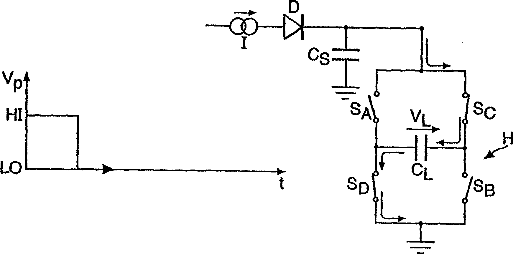
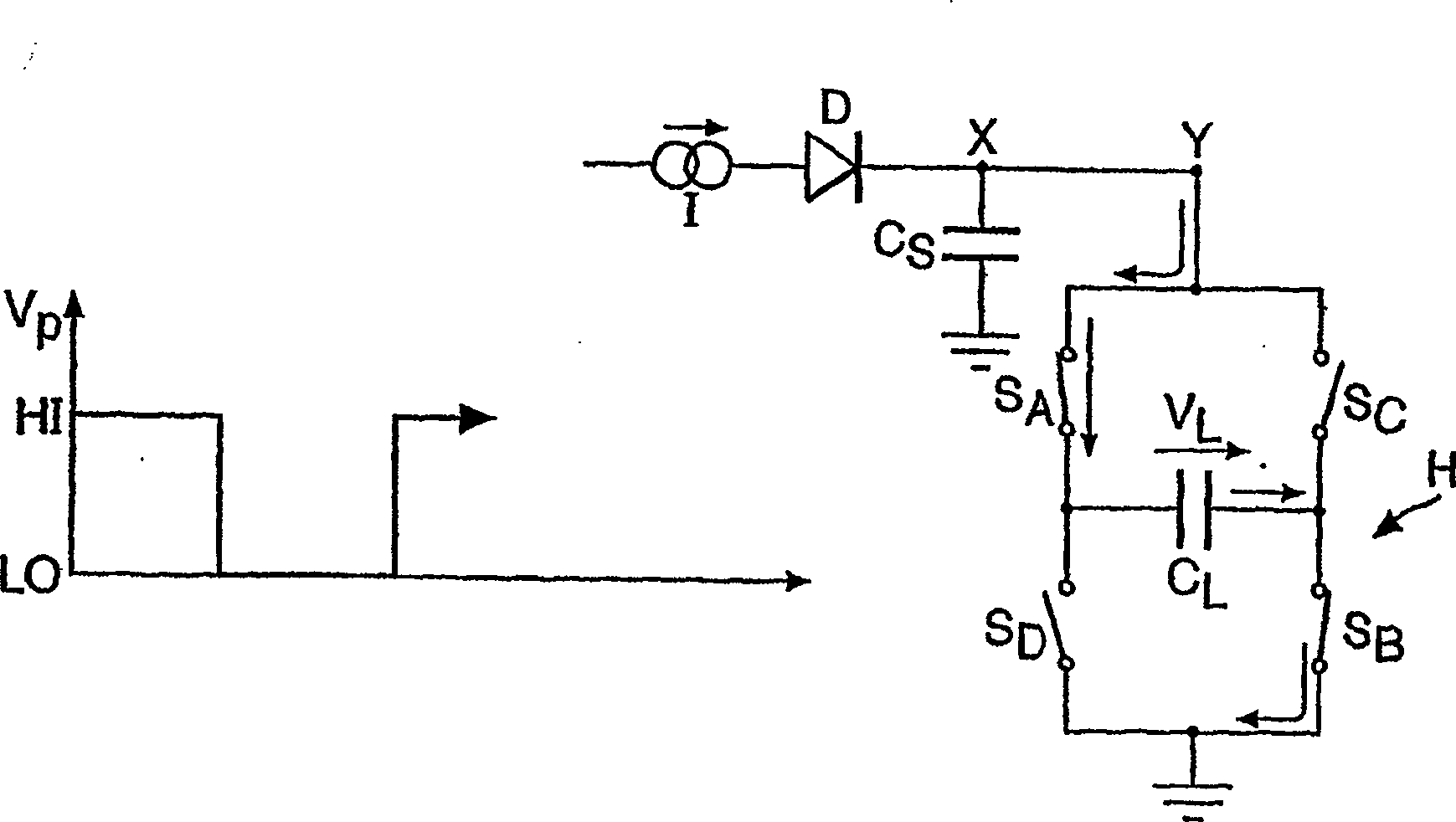
[0026] see Figure 1a , which shows a circuit according to the invention. The circuit comprises a current source I connected in series with a diode D and an H-bridge structure H. A smoothing capacitor Cs is provided in parallel with the H-bridge structure and connected to ground potential.

[0027] Figure 1a The H bridge structure H in includes 4 switching elements S A -S D , for simplicity, they are represented as simple switches. In a practical circuit, the switch S A -S D Provided by Field Effect Transistors (FETs). The H-bridge consists of two parallel branches, each with two switches S arranged in series A , S D and S C , S B . A capacitive load in the form of an electroluminescent lamp C L The nodes on each branch between the switches of the branch are connected between the branches of the H-bridge. One end of the H-bridge is connected to the ground potential.

[0028] Switch S A -S D The position of the polarity voltage V P control, the voltage variatio...


PUM


Abstract

A control circuit for an electroluminescent display in which a high-voltage AC current is supplied from a low-voltage DC source to a capacitive load using a flyback converter and an H-bridge. The capacitive load discharges whenever the polarity of the capacitive load is reversed. This high voltage discharge is stored on the low voltage capacitor, which is then used as an auxiliary power supply for powering the switching elements of the control circuit.

Description

technical field [0001] This invention relates to electroluminescent displays and their controllers, and more particularly to the power supplied to the control circuits. Background technique [0002] Electroluminescent displays have selectively illuminated areas for displaying information. The advantage of such displays is that they can be large, bendable and relatively low cost compared to competing technologies. [0003] Although electroluminescent lamps have been known since the 1950s, they have a short life and bendable electroluminescent devices were not developed until the 1980s. However, it is used as LCD backlight and only recently have actual electroluminescent displays become available. [0004] Electroluminescent displays generally include a layer of fluorescent material, such as doped zinc sulfide powder, between two electrodes. Typically at least one electrode consists of a transparent material such as indium tin oxide (ITO) provided on a transparent substrate...

Claims


Application Information

Patent Timeline
Patent Type & Authority Patents(China)
IPC IPC(8): G09G3/30H05B33/08H05B44/00
CPCG09G3/30H05B33/08Y02B20/325G09G2330/023Y02B20/30H05B45/325H05B45/37H05B45/385H05B44/00H02M3/07H02M7/48H05B45/00
Inventor 克里斯·弗赖尔
Owner PELIKON
Why Eureka
Try Eureka