
Machinery suspension device
A kind of suspension device and mechanical technology, applied in mixers, mixers with rotating containers, dissolution, etc., can solve the problems of high production cost, inconvenient operation and control, complex structure, etc., to improve operational efficiency and increase operational stability , The effect of prolonging the life of the equipment
- Summary
- Abstract
- Description
- Claims
- Application Information
AI Technical Summary
Problems solved by technology
Method used
Image


Examples
Embodiment Construction
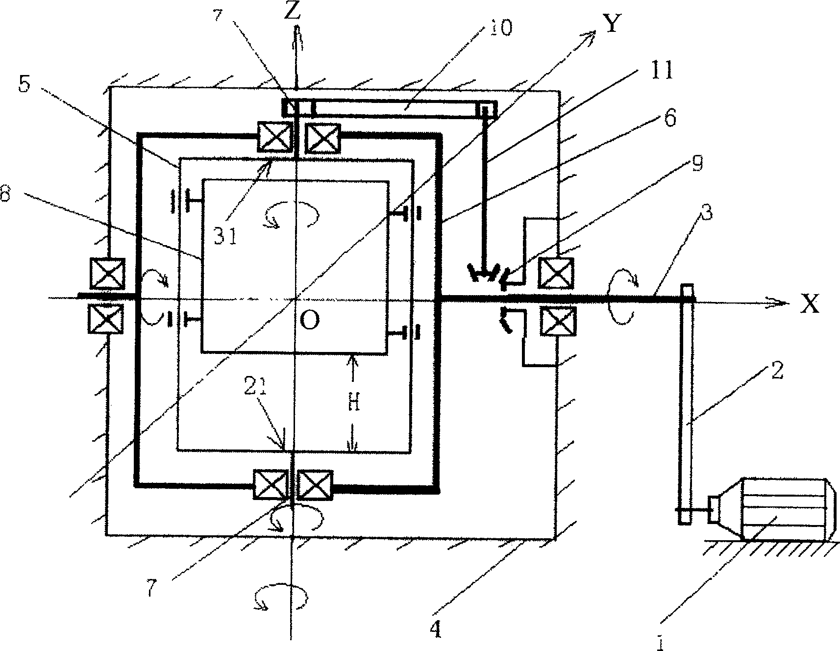
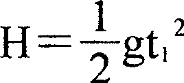
[0009] See figure 1 , the mechanical suspension device includes a motor 1, a transmission pair 2 and a transmission shaft 3 connected to the transmission pair 2, the motor 1, the transmission pair 2 and the transmission shaft 3 constitute a driving device, the transmission shaft 3 is pivotally connected to a support body 4, and the support body 4 The function is to provide support for the transmission shaft 3 and provide a working space for the suspension device. The transmission shaft 3 is connected to a frame structure 6 that can accommodate the outer rotation container 5, the frame structure 6 is connected to both ends of the rotation shaft 7 of the outer rotation container 5, the transmission shaft 3 drives the outer rotation container 5 to rotate on the Y-Z plane around the X axis, called revolution. An inner rotating container 8 coaxial with the outer rotating container 5 is arranged inside the outer rotating container 5. The inner rotating container 8 and the outer rot...
PUM
 Abstract
Description
Claims
Application Information