Device for generating alternating light effects

A technology of light effect and ignition device, applied in fluid-driven electric lighting devices, lighting devices, light sources, etc., can solve the problems that fireworks cannot be realized

Inactive Publication Date: 2009-09-30
INT EVENTLIGHTER
View PDF6 Cites 0 Cited by
  • Summary
  • Abstract
  • Description
  • Claims
  • Application Information

AI Technical Summary

Problems solved by technology

For the reasons mentioned above, this is generally not possible with known fireworks

Method used


Image

  • Device for generating alternating light effects
  • Device for generating alternating light effects
  • Device for generating alternating light effects

Examples


Embodiment Construction

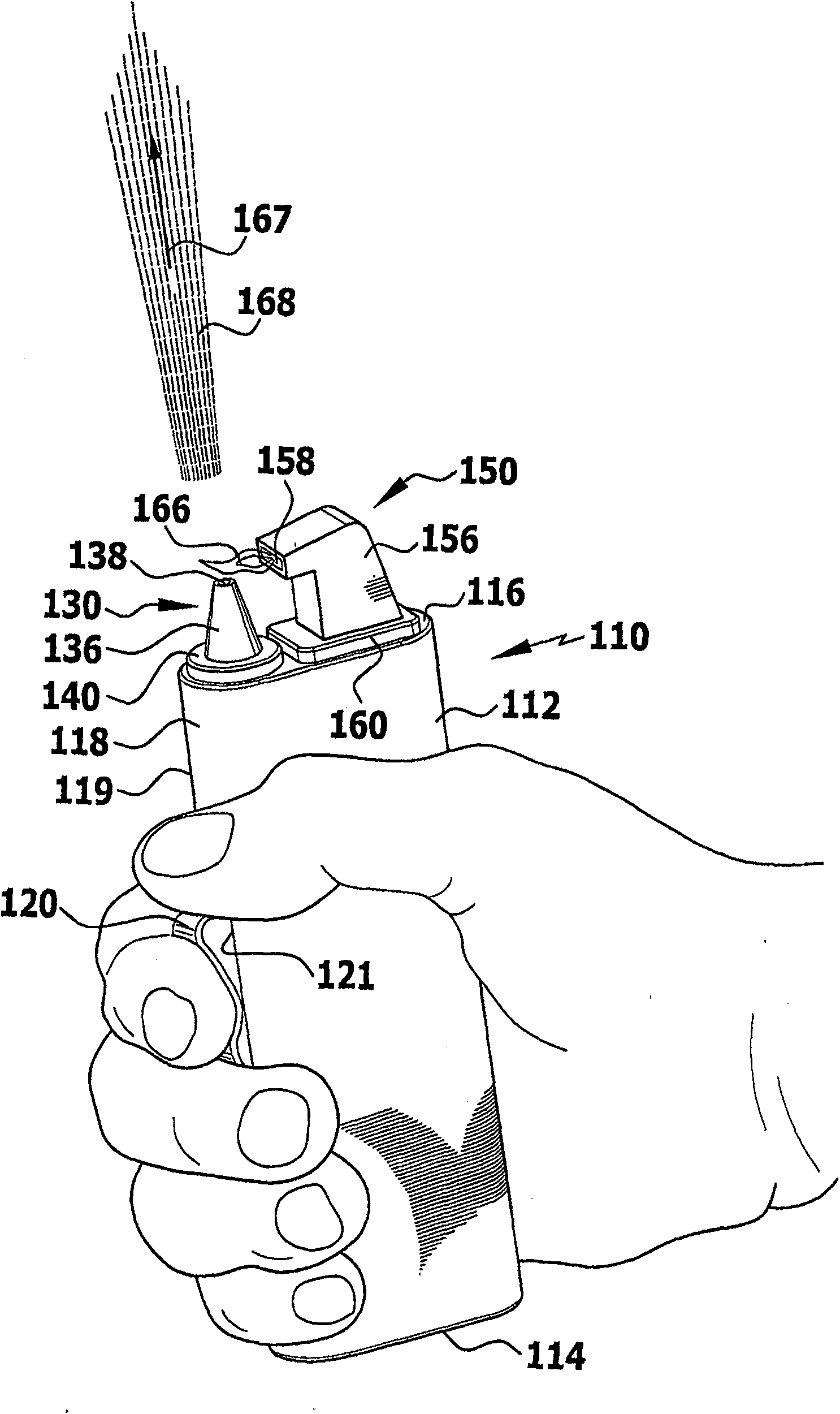
[0058] exist figure 1 A first embodiment of the device according to the invention is shown in and generally designated 110 . The device 110 includes a housing 112 having an eg oval base 114 , an oval top 116 and a tubular wall 118 having an outer surface 119 extending from the base 114 to the top 116 .

[0059] The housing 112 simultaneously serves as a grip element and is dimensioned such that it can be comfortably held in the hand. In this held position, the housing 112 is surrounded by the fingers with the thumb facing the top surface 116 of the housing 112 .

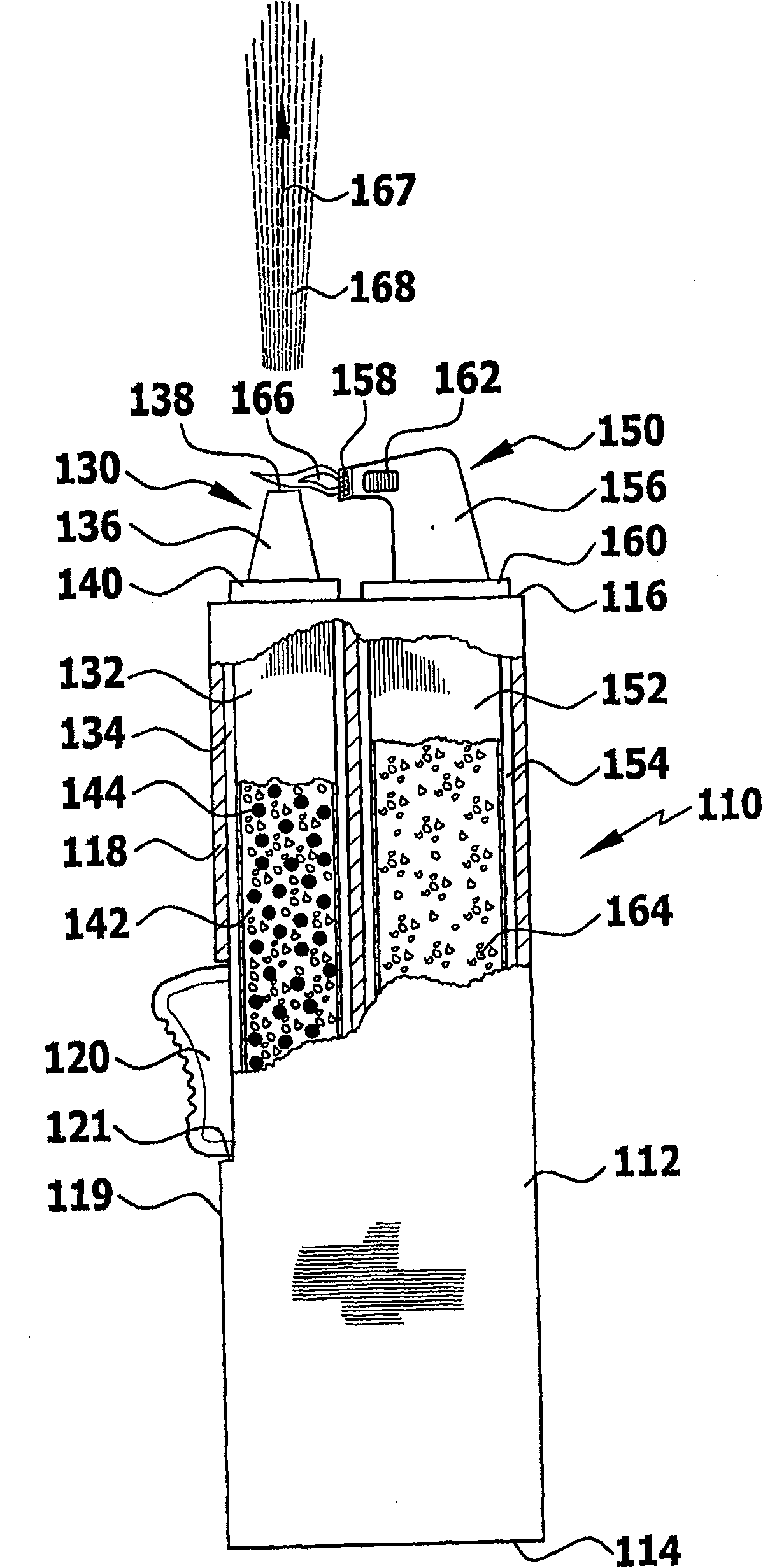
[0060] A mechanical actuating element 120 is arranged in the recess 121 of the side 118 , which can be pressed into the housing 112 by actuating it, for example with the index finger, in the hand-held position. exist figure 2 A device 110 is shown with a housing 112 partially cut away.

[0061] The device 110 includes an optical effect current generator 130 . The optical flow generator 130 comprises a cylindric...


PUM


Abstract

The aim of the invention is to provide a device for generating alternating light effects in a simple manner. To achieve this, the device comprises a grip element, a thermal activation unit and at least one light effect current generator with an exit opening, through which a component that produces the light effects can be expelled by means of a stream of carrier gas in a discharge direction. The component that produces the light effects can be activated by the thermal activation device.

Description

technical field [0001] The invention relates to a device for producing an alternating light effect. Background technique [0002] Different forms of fireworks for producing different light effects are known in the prior art. These are mostly devices for which, in order to use them without risk, a separate launching device is required, eg for rockets, or at least one fire-resistant stand surface, eg for volcanoes or the like. The use of such fireworks is therefore expensive and cannot be carried out without problems in all cases. For this purpose, a separate ignition device or the like in the form of a flame generating mechanism is required in known fireworks. [0003] During large events, festivals or other occasions, participants often need to produce alternating light effects in a simple way. This is generally not possible with known fireworks for the reasons mentioned above. [0004] Alternating light effects in the sense of the present application are understood to m...

Claims


Application Information

Patent Timeline
Patent Type & Authority Patents(China)
IPC IPC(8): F23Q2/16F23Q2/34
CPCF23Q2/42F21S10/04F23Q2/345F23Q2/165F21L13/02F21K5/00
Inventor P·哈夫纳
Owner INT EVENTLIGHTER
Why Eureka
Try Eureka