
Receiver with iterative channel estimation using a return loop (turbo estimation)

A channel evaluation and receiver technology, applied in multiplexing communications, baseband systems, digital transmission systems, etc., and can solve problems such as impossible channel modeling

Inactive Publication Date: 2010-02-24
FRANCE TELECOM SA
View PDF2 Cites 0 Cited by
  • Summary
  • Abstract
  • Description
  • Claims
  • Application Information

AI Technical Summary

Problems solved by technology

It should be noted that it is simply not possible to perfectly model the channel due to the noise of the receiver

Method used


Image

  • Receiver with iterative channel estimation using a return loop (turbo estimation)
  • Receiver with iterative channel estimation using a return loop (turbo estimation)
  • Receiver with iterative channel estimation using a return loop (turbo estimation)

Examples


Embodiment Construction

[0013] The proposed invention applies to any digital transmission system utilizing channel estimation, and in particular to mobile radio systems and wireless local area networks (WLAN).

[0014] In particular, the proposed general idea applies in a non-limiting manner to time division multiple access, regardless of whether the system is a multiple transmit multiple receive (MTMR) antenna configuration or a multiple input multiple output (MIMO) configuration (TDMA), Code Division Multiple Access (CDMA), Time Duplex CDMA (TD-CDMA, timeduplex CDMA), Wideband CDMA (W-CDMA), Orthogonal Frequency Division Multiplexing (OFDM) and Multicarrier CDMA (MC-CDMA) )system.

[0015] In the following description, particular attention needs to be paid to the channel estimator part of any iterative receiver, such as a turbo receiver. The described deployment is suitable for any receiver where channel estimation, symbol detection and decoding are performed in an iterative manner.

[0016] The ...


PUM


Abstract

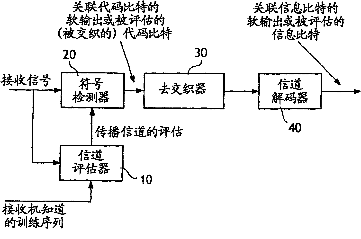
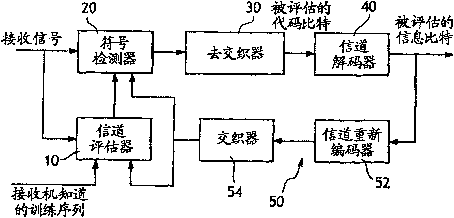
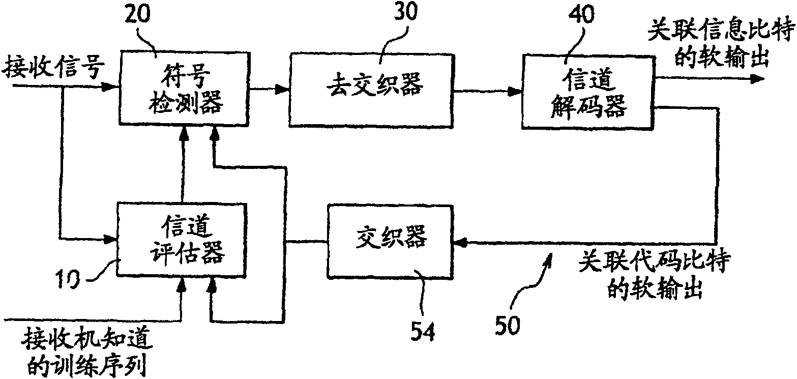
The invention concerns a receiver with data transmission channel turbo estimation, comprising at least one channel estimator (10) and a symbol detector (20), as well as a return loop (50) to the channel estimator (10) for returning transmission data such as they have been estimated by the symbol detector (20) upon a previous iteration. The invention is characterized in that the channel estimator (10) and the symbol detector (20) are designed to implement a series of operations each resulting in providing an estimation of at least one distinct transmission data, the channel estimator (10) beingdesigned to eliminate from a group of reception data one part thereof which is dependent upon the transmission data to be estimated, and, based on said reception dependence-free data, to provide a determination of the propagation channel itself dependence-free, the symbol detector (20) proceeding with the operation by estimating the transmission data from said propagation channel.

Description

technical field [0001] The invention relates to communication based on digital transmission by means of data packets (bit packets) which are previously coded by a channel coder (error correction coder). Background technique [0002] Due to propagation phenomena, the transmitted signal is substantially distorted. In order to recover the transmitted data (information bits), the effects of the propagation must be compensated. To this end, the propagation conditions, and more precisely the so-called "propagation channel", which characterizes the radio conditions, must be evaluated. [0003] The propagation channel model is a linear filter whose impulse response characterizes its properties. The quality assessed for the propagation channel will seriously affect the quality with which the receiver recovers its received data. It should be noted that due to the noise of the receiver it is not at all possible to perfectly model the channel. However, in order to obtain the best po...

Claims


Application Information

Patent Timeline
Patent Type & Authority Patents(China)
IPC IPC(8): H04L25/02H04B1/69H04B1/7097H04J99/00
CPCH04L25/0236
Inventor J·原-吴S·拉绍尔斯
Owner FRANCE TELECOM SA
Learn More