Hot-air blower

A technology of hair dryer and hot air, which is applied in the direction of instant heating clips, clothing, hairdressing equipment, etc., and can solve the problems of reduced cooling efficiency of discharge electrodes, unstable generation of nano-sized mist, and heating

Inactive Publication Date: 2007-07-25
MATSUSHITA ELECTRIC WORKS LTD
View PDF1 Cites 9 Cited by
  • Summary
  • Abstract
  • Description
  • Claims
  • Application Information

AI Technical Summary

Problems solved by technology

However, in this case, there is a possibility that, when the entire airflow in the ion flow channel is made to flow toward the discharge electrode, the discharge electrode is heated by the airflow, and the cooling efficiency of the discharge electrode is lowered, so that the nano-sized Fog generation becomes erratic

Method used


Image

  • Hot-air blower
  • Hot-air blower
  • Hot-air blower

Examples


no. 1 example

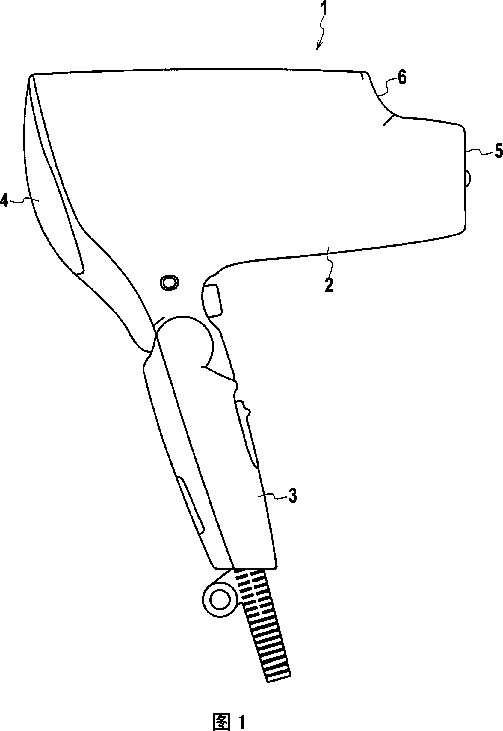
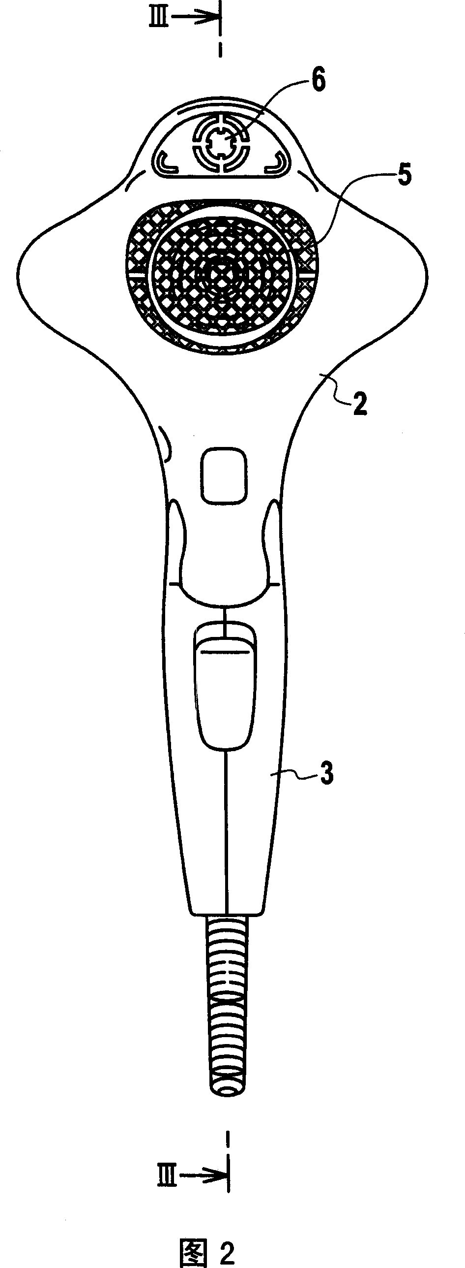
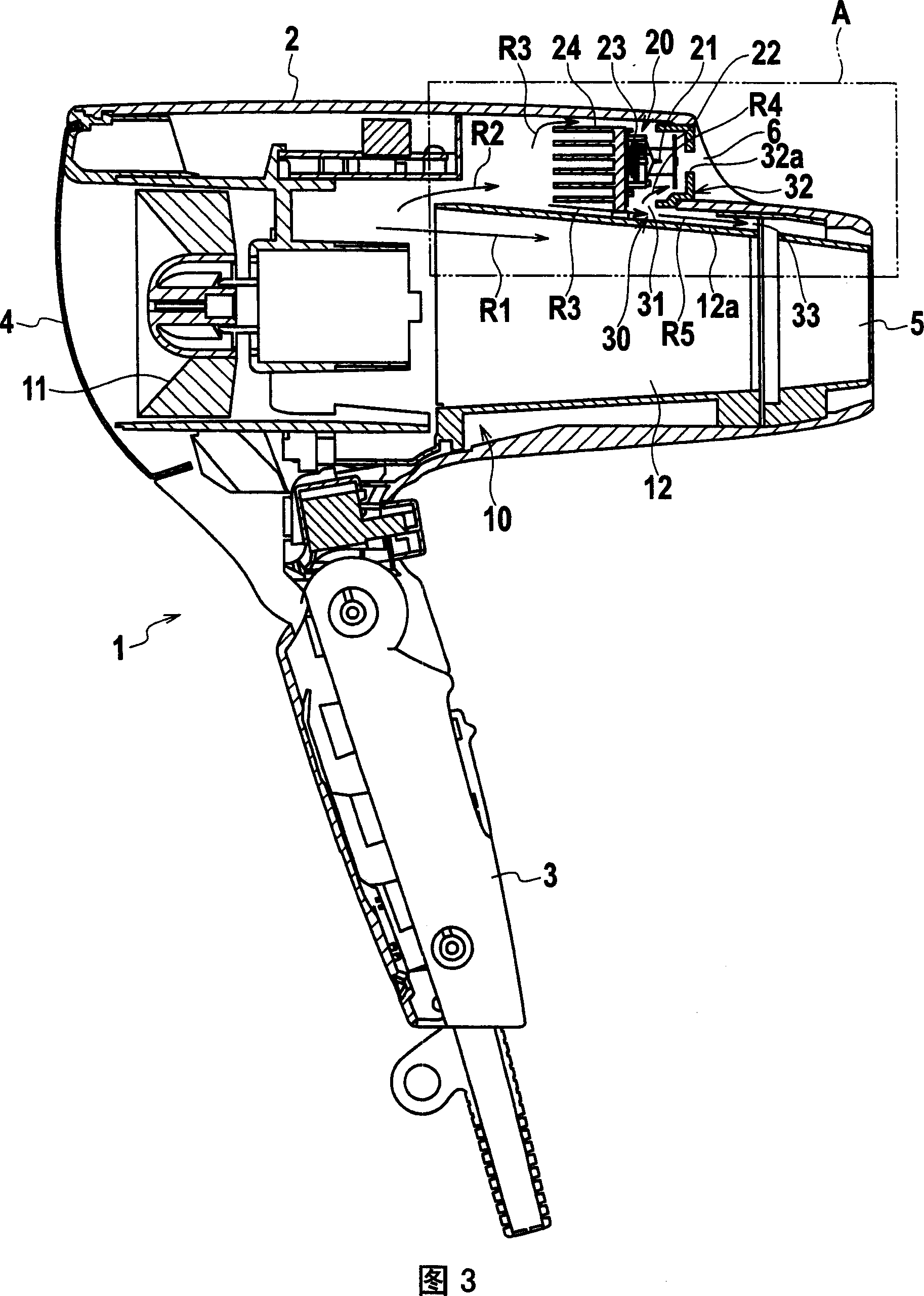
[0017] Fig. 1 is a side view of a dryer which is an example of a hot air blower, Fig. 2 is a front view of the dryer, Fig. 3 is an enlarged sectional view of the dryer taken along line III-III in Fig. 2 , and Fig. 4 is an enlarged sectional view of part A in FIG. 3 .

[0018] As shown in FIGS. 1 and 2, in the dryer 1 as the hot air blower according to the present embodiment, the handle 3 is foldably attached to the lower portion of the cover 2, and the inlet 4 is formed at the rear end of the cover 2. A discharge port 5 is formed at the distal end of the cover body 2 . An ion mist discharge port 6 is also formed at the upper end portion of the cover 2 so as to be in the same direction as the discharge port 5 .

[0019] As shown in Fig. 3, be provided with main unit block 10 in cover body 2, main unit block 10 comprises: the fan 11 that acts as blowing unit, fan 11 takes in outside air from inlet 4, to blow outside air from outlet. 5 discharge; and a heater 12 serving as a he...

no. 2 example

[0039] Fig. 5 is an enlarged sectional view of a relevant portion of a dryer according to a second embodiment, which is a view similar to Fig. 4 . The dryer according to this embodiment has the same constituent elements as the dryer according to the first embodiment. Therefore, these same constituent elements are denoted by like reference numerals, and redundant description thereof will be omitted.

[0040] As shown in FIG. 5, the configuration of the dryer 1A according to the present embodiment is basically the same as that of the dryer 1 of the first embodiment, and here, the electrostatically atomizing block 20 is arranged in the heat dissipation flow channel R2 branched from the main air flow channel R1 Inside, the part of the heat dissipation flow channel R2 located on the downstream side of the electrostatic atomization block 20 is branched into a first branch flow channel R4 and a second branch flow channel R5, and the air supply adjustment unit 30A is arranged in the f...


PUM


Abstract

A radiation flow passage is branched from a main air flow passage extending from a fan in a main unit block toward a heater, an electrostatic atomization block is disposed in the radiation flow passage, and a section of the radiation flow passage positioned on a downstream side of a radiating unit is branched to a first branched flow passage passing through a discharge electrode to communicate with outside and a second branched flow passage bypassing the discharge electrode to communicate with the outside, so that the air around the discharge electrode is always ventilated to facilitate generation of water droplets, and portion of the air introduced into the radiation flow passage is supplied to the discharge electrode by the first branched flow passage to suppress lowering of cooling efficiency of the discharge electrode, so that nanometer-sized mist can be stably generated.

Description

technical field [0001] The invention relates to a hot air blower with electrostatic atomization function. Background technique [0002] As a conventional hot air hair dryer with an electrostatic atomization function, for example, there is a hair dryer. The hair dryer has a structure in which an inlet and an outlet are formed in the housing, and the heater is arranged on the downstream side of an air flow channel that takes in external air from the inlet and sends air from the outlet through a fan. discharge, thereby, the air is heated by the heater, and the hot air is discharged from the discharge port, and the hair dryer also has such a structure that the ion generator is arranged in the ion flow channel branched from the air flow channel, so that the ion Negative ions generated in the generator are discharged from the ion discharge port (for example, see Japanese Patent Application Laid-Open No. 2002-191426 (page 3 and FIG. 1 )). [0003] In a hot air hair dryer with an ...

Claims


Application Information

Patent Timeline
Patent Type & Authority Applications(China)
IPC IPC(8): A45D20/12A45D20/10
CPCA45D2001/008A45D20/12A45D2200/202
Inventor 田中秀树三原史生石川朋哉松井康训
Owner MATSUSHITA ELECTRIC WORKS LTD
Why Eureka
Try Eureka