Fluid filled vibration damping device and method of producing the same

A vibration-damping device and fluid-sealing technology, applied in shock absorbers, power units, jet propulsion devices, etc., can solve problems such as damage to sealing rubber

Inactive Publication Date: 2007-08-08
SUMITOMO RIKO CO LTD
View PDF5 Cites 19 Cited by
  • Summary
  • Abstract
  • Description
  • Claims
  • Application Information

AI Technical Summary

Problems solved by technology

However, a fixing structure that relies on press-fitting tends to cause damage to the seal rubber, for example, when press-fitting

Method used


Image

  • Fluid filled vibration damping device and method of producing the same
  • Fluid filled vibration damping device and method of producing the same
  • Fluid filled vibration damping device and method of producing the same

Examples


Embodiment Construction

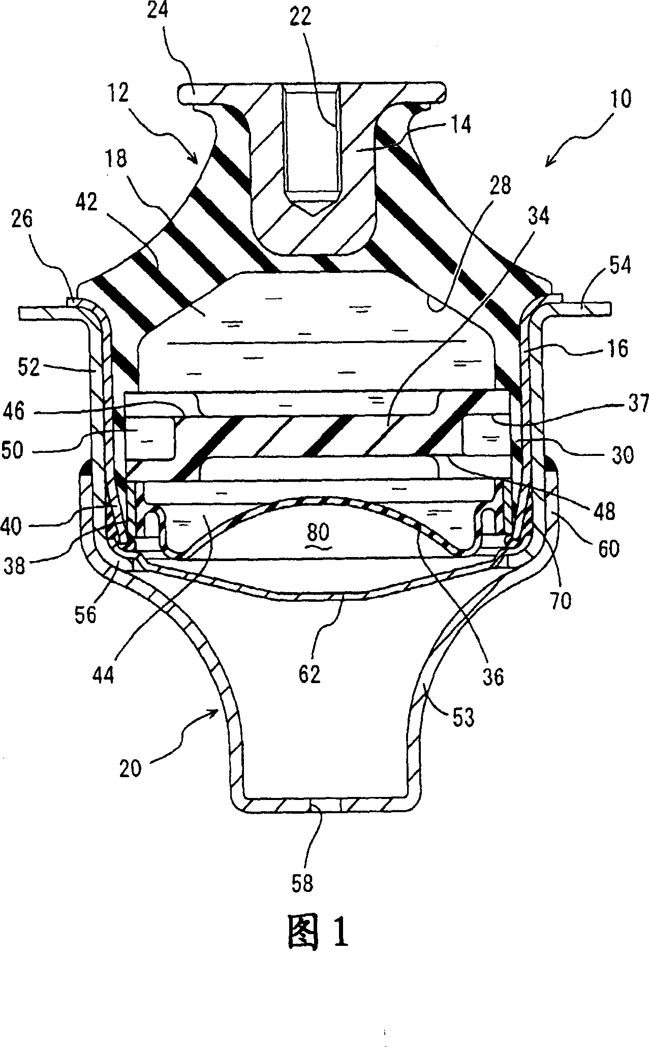
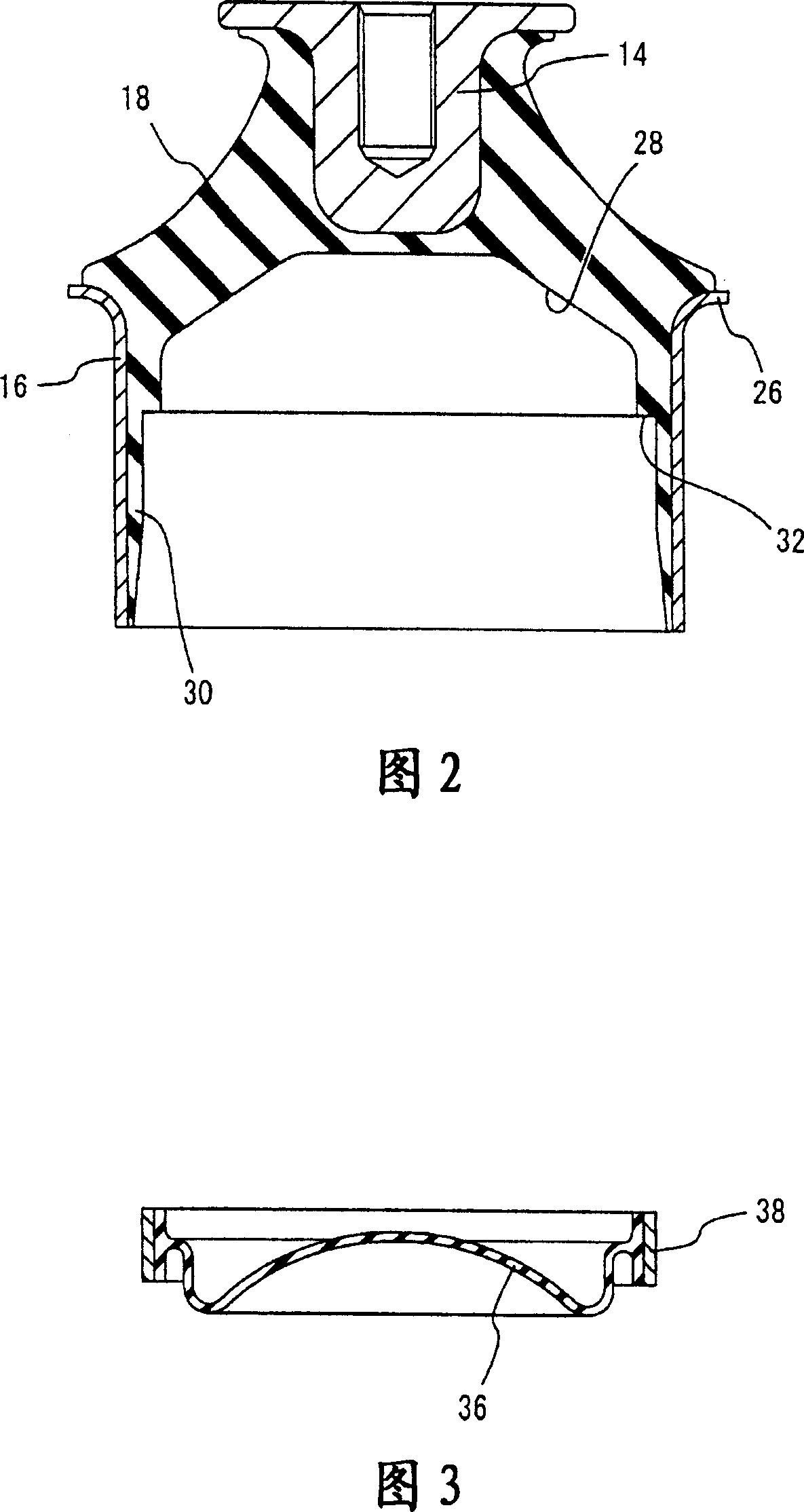
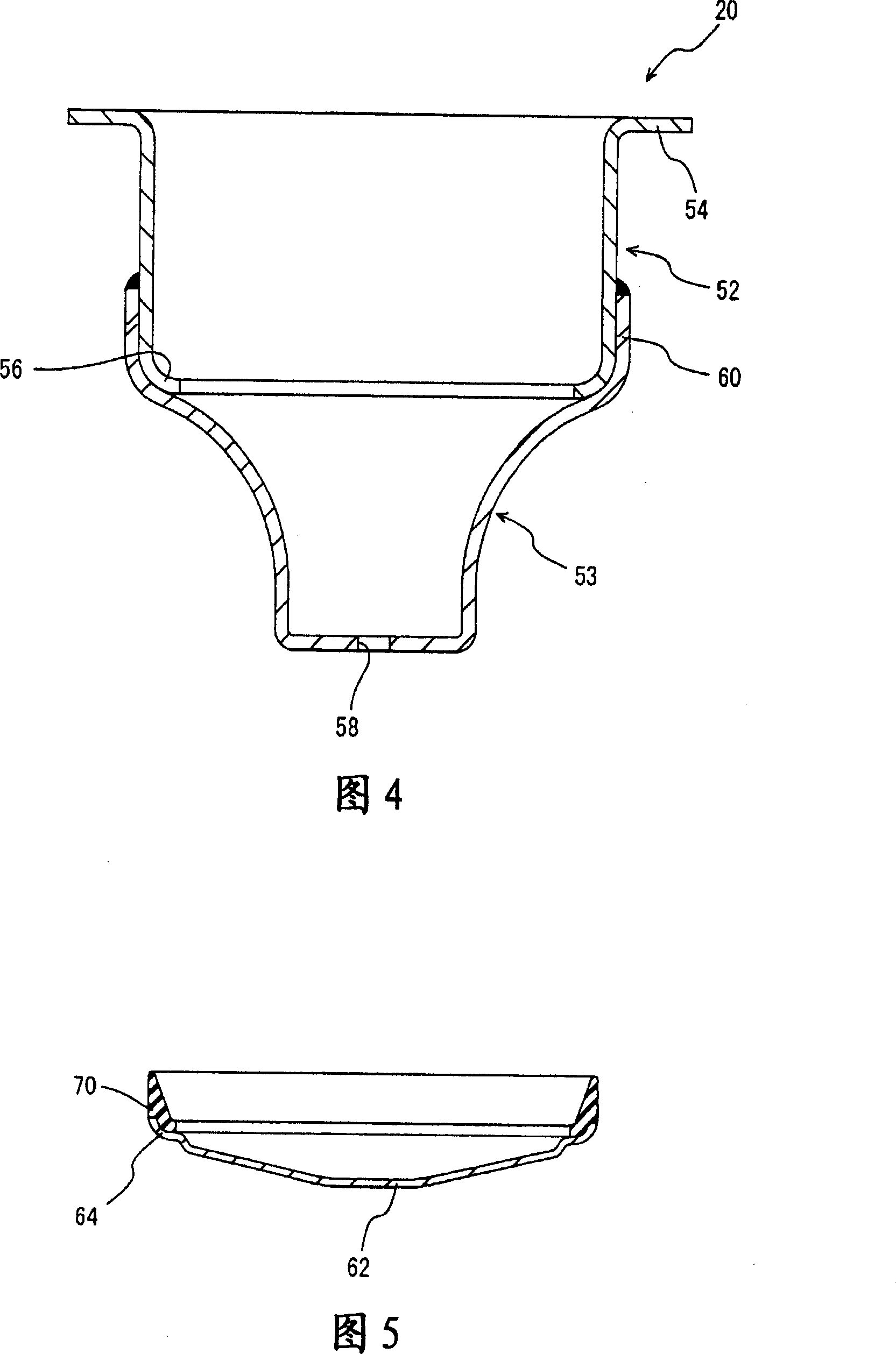
[0057] Referring first to FIG. 1, there is shown an automobile engine mount 10 belonging to a fluid-enclosed vibration damping device according to a first embodiment of the present invention. This engine mount 10 consists of a first metal mount 14 and a second metal mount 16 , which are elastically connected by a main rubber-elastic body 18 . Although not shown in the drawings, the first mount 14 is attached to the power unit assembly side, and the second mount 16 is attached to the vehicle body side of the vehicle through a bracket 20 as a holding member, so that the power unit assembly It is supported on the vehicle body in a vibration-damping manner. In the following description, the vertical direction refers in principle to the vertical direction in FIG. 1 , which represents the substantially vertical direction of the mounted mounting, ie the input direction of the main vibration load.

[0058] More specifically, the first mount 14 is a vertically extending block having a...


PUM


Abstract

A fluid filled vibration damping device including an elastic body connecting a first and second mounting member, a pressure-receiving chamber defined by the elastic body and an equilibrium chamber defined by a flexible rubber film. The second mounting member is press fitted into a tubular holder member having an annular holding portion integrally formed at its lower end projecting radially inwardly. A cover plate member having an outside diameter smaller than an inside diameter of the holder member is disposed within the holder member with an outer peripheral portion is fixedly clamped by the second mounting member and the annular holding portion. A sealing rubber is disposed for fluid-tightly closing a gap formed between the clamped portion so that an tightly closed air chamber defined by the cover plate member is formed on a back side of the flexible rubber film.

Description

[0001] cross reference [0002] The entire disclosures of the specification, drawings and abstract of Japanese Patent Application No. 2006-023658 filed on January 31, 2006 and Japanese Patent Application No. 2006-267400 filed on September 29, 2006 are incorporated herein by reference. technical field [0003] The present invention relates to a fluid-enclosed vibration-damping device capable of exhibiting a vibration-damping effect based on the flow action of a sealed incompressible fluid, which flows through a connection between a pressure-bearing chamber and a balance chamber, and a method for manufacturing the same. orifice passage. Background technique [0004] Fluid-enclosed vibration damping capable of exhibiting a damping effect based on resonance or other flow action or properties of the incompressible fluid enclosed within it is known in the prior art for installation between components that make up a vibration transmission system Devices, such as damping supports o...

Claims


Application Information

Patent Timeline
Patent Type & Authority Applications(China)
IPC IPC(8): F16F13/00B60K5/12
Inventor 南泽忠光
Owner SUMITOMO RIKO CO LTD
Why Eureka
Try Eureka