Multi-stage whirlwind separating device of vacuum cleaner

A technology of cyclone separation device and cyclone separator, which is used in suction filters and other directions

Inactive Publication Date: 2007-08-15
ECOVACS ROBOTICS (SUZHOU ) CO LTD
View PDF1 Cites 54 Cited by
  • Summary
  • Abstract
  • Description
  • Claims
  • Application Information

AI Technical Summary

Problems solved by technology

[0002] In the prior art, the multi-stage cyclone separation device of the vacuum cleaner at least includes a primary cyclone separator located upstream and a secondary cyclone separator located downstream of the primary cyclone separator. The primary cyclone separator includes an inner bottom with a primary collector. The primary separation bucket of the dust chamber, the secondary cyclone separator includes a secondary separation bucket with a secondary dust collection chamber at the inner bottom; the U.S. Patent No. US6344064 discloses that the separation bucket is disassembled from the dust bucket, and then the The separation barrel is turned upside down so that the dust is poured out from the upper part. Although this method can simultaneously empty the dust in the primary dust collection chamber and the secondary dust collection chamber, in the multi-stage cyclone separation device, since most of the dust is separated by the primary cyclone Or the filter stays in the primary dust collection room, only a very small part of the dust will stay in the secondary dust collection room, so it is not necessary to empty the secondary dust collection room every time the primary dust collection room is emptied

Method used


Image

  • Multi-stage whirlwind separating device of vacuum cleaner
  • Multi-stage whirlwind separating device of vacuum cleaner
  • Multi-stage whirlwind separating device of vacuum cleaner

Examples


Embodiment 1

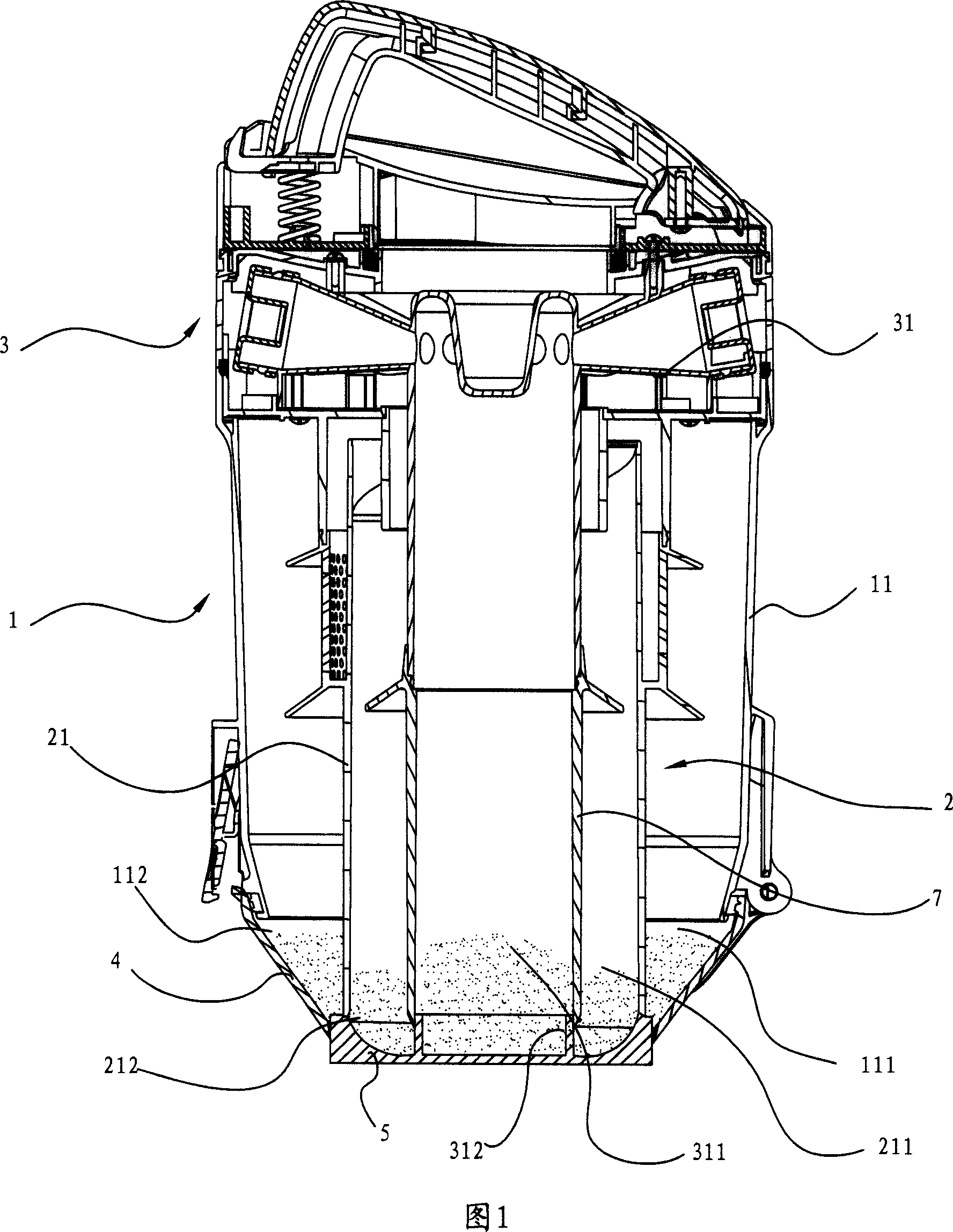
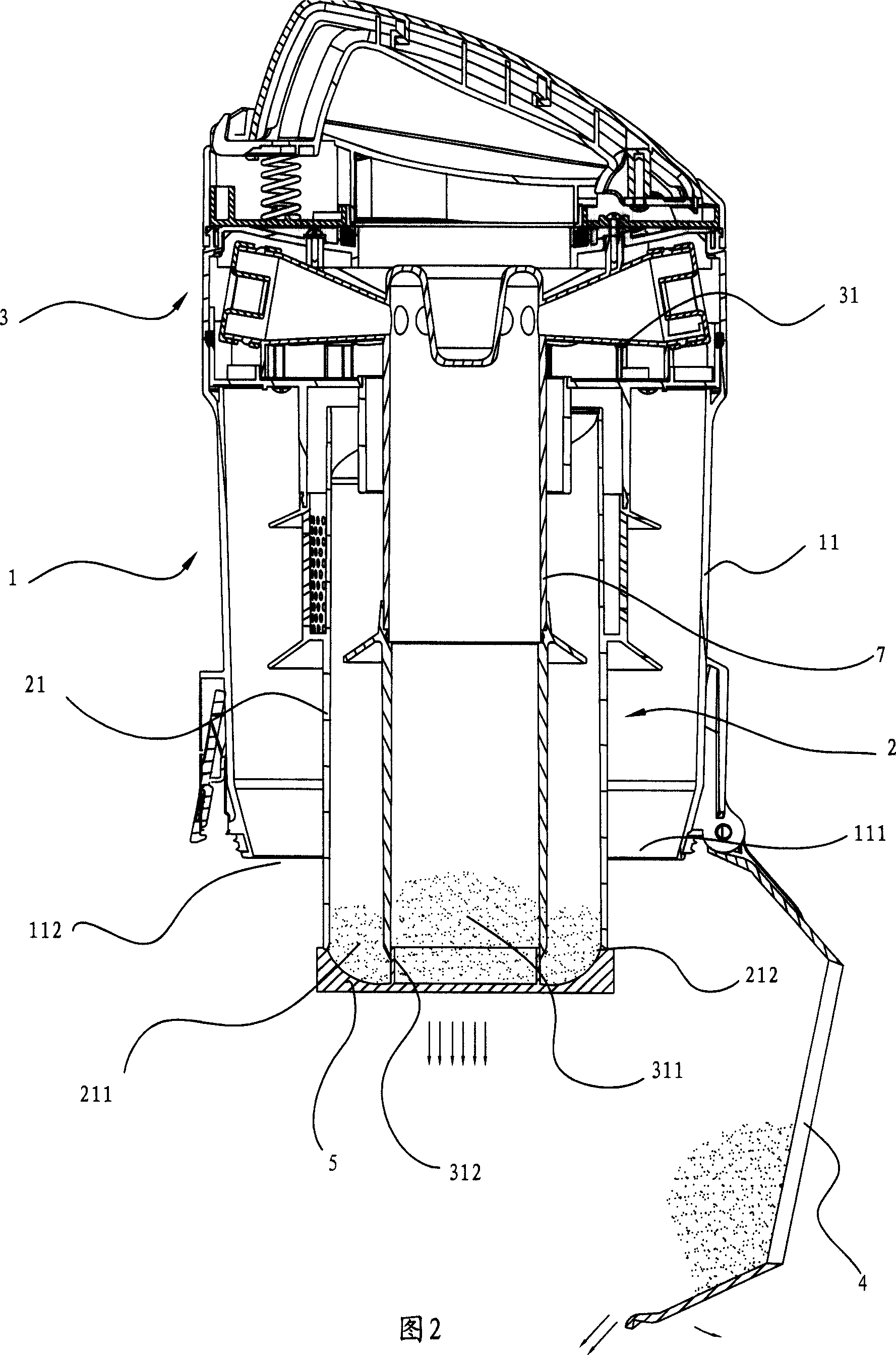
[0019] Referring to the multi-stage cyclone separation device of a vacuum cleaner shown in accompanying drawings 1-2, it is a three-stage cyclone separation device, which has a primary cyclone separator 1 located upstream and a secondary cyclone located downstream of the primary cyclone separator 1. Separator 2 and the three-stage cyclone separator 3 located downstream of the secondary cyclone separator 2, the air inlet 10 is arranged on the primary cyclone separator 1; wherein, the secondary cyclone separator 2 is located on the inside of the primary cyclone separator 1 The first-stage cyclone separator 1's diversion body is also the outer barrel of the second-stage cyclone separator 2; The lines lie on the same conical surface, and the conical point of the conical surface is roughly located on the axis of the secondary cyclone separator 2 .

[0020] The primary cyclone separator 1 comprises a primary separation barrel 11 whose lower part is a primary dust collection chamber ...

Embodiment 2

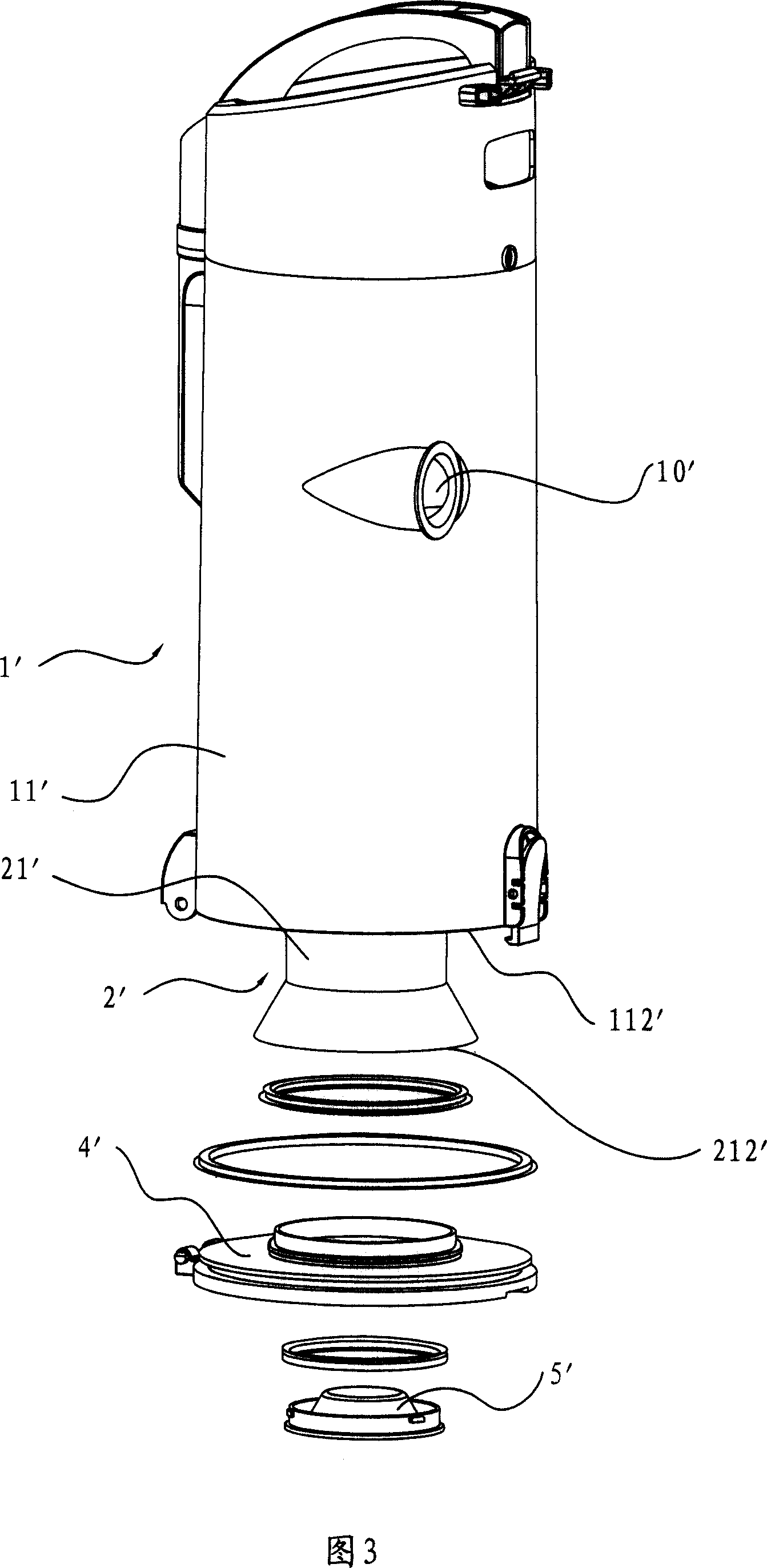
[0025] A multi-stage cyclone separation device of a vacuum cleaner as shown in Figure 3, this is a secondary cyclone separation device, with a primary cyclone separator 1 ' positioned upstream, a secondary cyclone separator positioned downstream of the primary cyclone separator 1 ' device 2' and the third-stage cyclone separator 3' downstream of the secondary cyclone separator 2', the air inlet 10' is arranged on the first-stage cyclone separator 1'; wherein, the second-stage cyclone separator 2' is located at the first-stage cyclone separator The inner part of the separator 1', the guide body of the primary cyclone separator 1' is also the outer barrel of the secondary cyclone separator 2';

[0026] The primary cyclone separator 1' includes a primary separation bucket 11' whose lower part is a primary dust collection chamber 111', and the secondary cyclone separator 2' includes a secondary separation bucket 21' whose lower part is a secondary dust collection chamber 211'. The...

Embodiment 3

[0030] The difference between the third embodiment and the second embodiment is only in the arrangement of the bottom covers of the dust buckets at all levels, as shown in Figure 4. Primary cyclone 1" pivot connection.


PUM


Abstract

The invention discloses a multi-staged cyclone separating device, which consists of one-grade upstream cyclone separator and two-grade downstream cyclone separator, wherein the inlet hole is set on the one-grade cyclone separator; the bottom of one-grade cyclone separator is one-grade dust-collecting chamber; the bottom of two-grade cyclone separator is two-grade dust-collecting chamber; the hole of one-grade and two-grade dust-collecting chambers possess bottom lids of one-grade and two-grade dust barrel; when the dust is collecting, the dust barrel bottom lid closes and vice versa; the bottom lids of one-grade and two-grade barrels are opened individually to pour ash, which opens lids of one-grade dust bottom and two-grade dust bottom sequently.

Description

technical field [0001] The invention relates to a multistage cyclone separation device of a vacuum cleaner. Background technique [0002] In the prior art, the multi-stage cyclone separation device of the vacuum cleaner at least includes a primary cyclone separator located upstream and a secondary cyclone separator located downstream of the primary cyclone separator. The primary cyclone separator includes an inner bottom with a primary collector. The primary separation bucket of the dust chamber, the secondary cyclone separator includes a secondary separation bucket with a secondary dust collection chamber at the inner bottom; the U.S. Patent No. US6344064 discloses that the separation bucket is disassembled from the dust bucket, and then the The separation barrel is turned upside down so that the dust is poured out from the upper part. Although this method can simultaneously empty the dust in the primary dust collection chamber and the secondary dust collection chamber, in ...

Claims


Application Information

Patent Timeline
Patent Type & Authority Applications(China)
IPC IPC(8): A47L9/16
Inventor 钱东奇
Owner ECOVACS ROBOTICS (SUZHOU ) CO LTD
Why Eureka
Try Eureka