Welded in plastic spout part

A part and plastic technology, applied in the field of welded plastic pouring parts, can solve the problem of easy deformation of the film, and achieve the effect of continuous welding

Inactive Publication Date: 2007-08-15
GEORG MENSKHEN GMBKH & KO KG
View PDF1 Cites 1 Cited by
  • Summary
  • Abstract
  • Description
  • Claims
  • Application Information

AI Technical Summary

Problems solved by technology

But this leads to, due to the high temperature and

Method used


Image

  • Welded in plastic spout part
  • Welded in plastic spout part
  • Welded in plastic spout part

Examples


Embodiment Construction

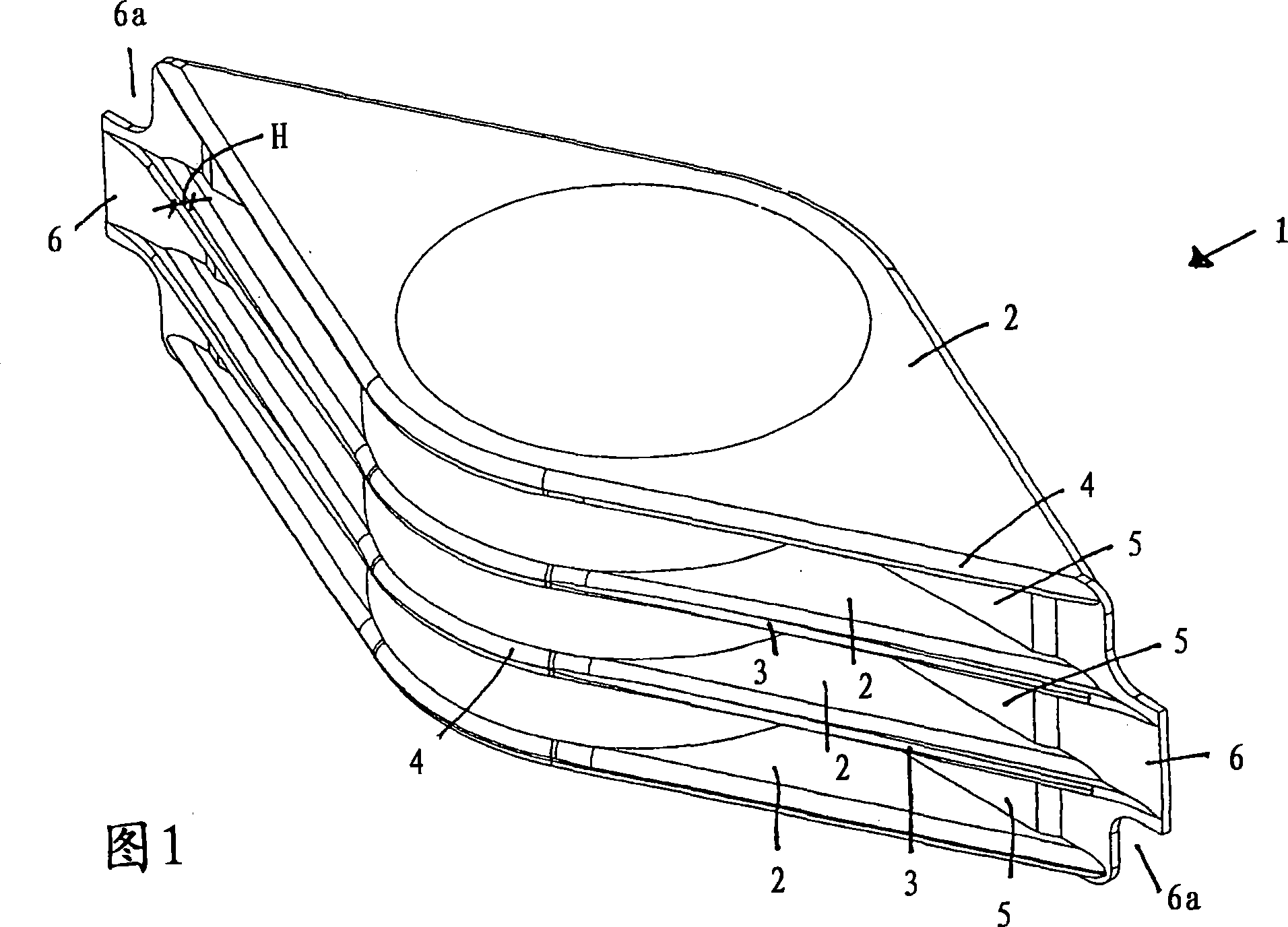
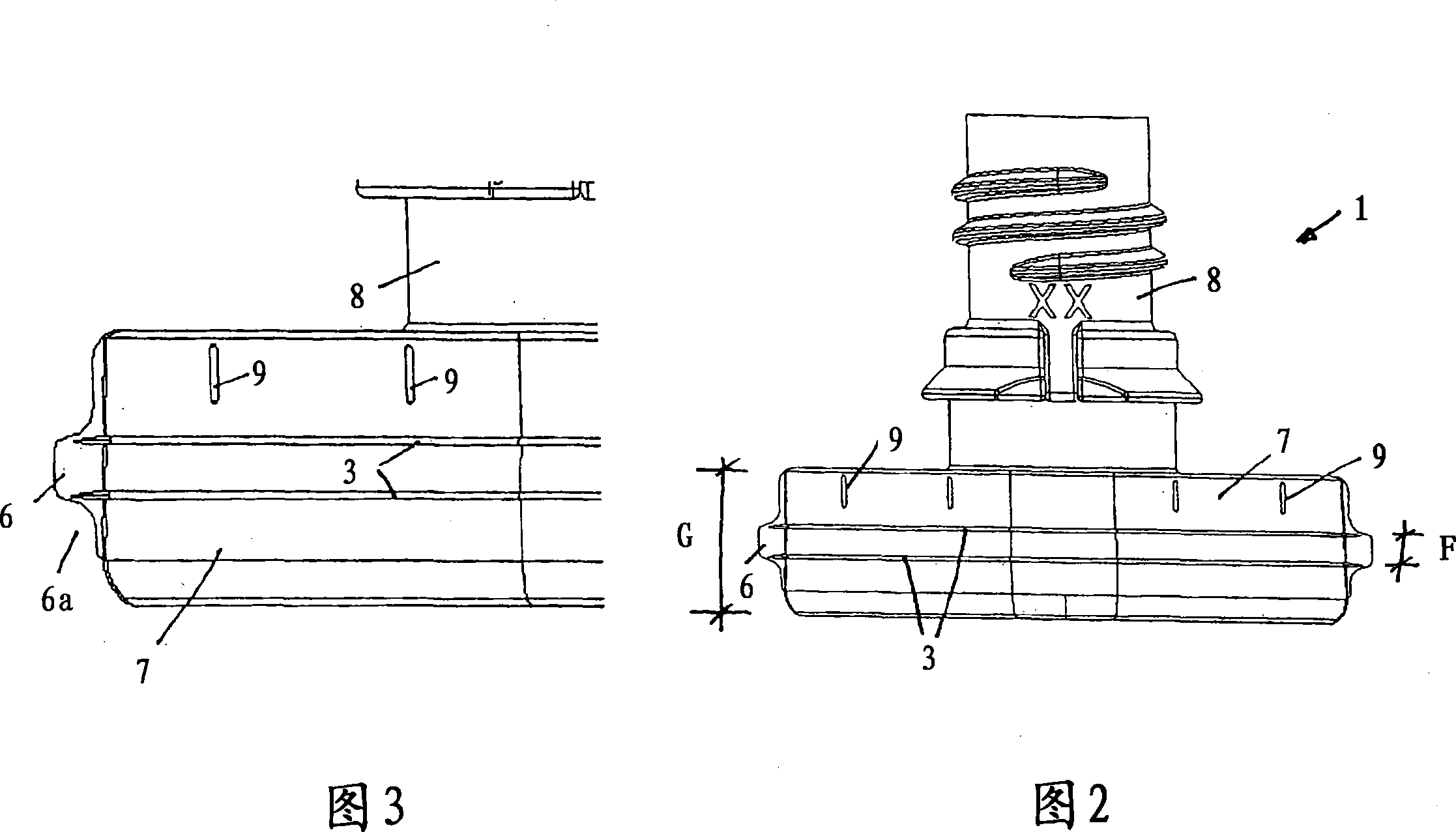
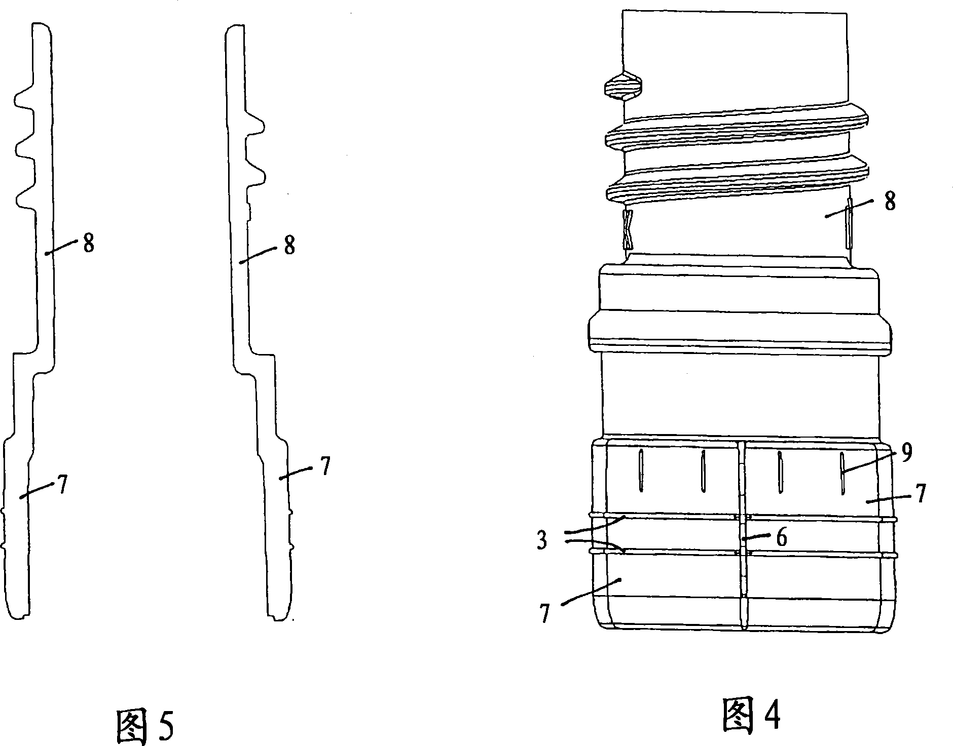
[0019] A welded boat-shaped plastic pouring part 1 is integrally formed from a dimensionally stable plastic and in a first embodiment has four mutually parallel substantially rhombic bases which are at equal distances from one another and are hereinafter referred to as "Welding Rib 2". Each of these planar welding ribs 2 comprises a rib base area, on the outer edge of which the respective welding ridge 3 is formed. The welding ridges 3 therefore protrude on the rounded front side of the rib base region and have a smaller thickness than the rib base region. But the welding ridges 3 of each rib shape do not extend along the full length of the side edge or the peripheral edge 4 of the welding rib 2, but in the central area extending through a central through hole of the welding rib 2, each The side edges and thus the outer edges of the welding ribs are rounded and have no welding ridges.

[0020] The purpose of the through hole in the center of the welding part 1 is to accommod...


PUM


Abstract

The invention relates to a welded-in plastic spout part that is to be joined to a plastic receptacle part, especially a receptacle part made of film-type plastic material such as a pouch. The inventive spout part comprises parallel planar weld-on ribs which extend along the circumference of a neck area (spout) that defines a pouring passage. A rib-shaped welding burr that is less thick than the weld-on ribs is provided at the outer circumference of said weld-on ribs. The welding burr is molded onto an outer rounded peripheral edge of the weld-on ribs. A partition which protrudes radially on both sides of the neck area is arranged perpendicular to the weld-on ribs. Both ends of said partition extend beyond the ends of the rib base area so as to form lateral flaps. The welding burrs extend past both sides of the flaps while the lateral flaps are provided with one respective recess instead of a top and bottom outer corner.

Description

technical field [0001] The invention relates to a welded plastic pouring part for connection to a plastic container part, especially a container part of film-like plastic, which pouring part comprises mutually extending circumferentially in a neck region defining a pouring channel. For each parallel welded rib, a rib-shaped welded ridge with a beveled surface and a thickness smaller than that of the base area of ​​the rib is arranged on its outer circumference, wherein the welded ridge is formed on the base area of ​​the rib On an outer rounded peripheral edge and perpendicularly to the welding rib, a partition wall is arranged, which protrudes radially to both sides of the neck region. Background technique [0002] One such weldment is known from EP 0 773 893 B1. In this known embodiment, the rib-shaped welding ridge terminates at the outer end of the welding rib. The ends of the weld ribs and weld ridges thus form a seamless location where tight welding of the bag film i...

Claims


Application Information

Patent Timeline
IPC IPC(8): B65D33/38
Inventor 德特勒夫・希尔德布兰德瓦尔特・舒尔特
Owner GEORG MENSKHEN GMBKH & KO KG
Why Eureka
Try Eureka