Liquid crystal display device, driving control circuit and driving method used in same

A liquid crystal display device, driven technology, applied in TV, electrical components, color TV, etc., can solve problems such as burnt screen, display data voltage polarity deviation, power increase, etc., and achieve the effect of eliminating flickering and reducing animation blur

Inactive Publication Date: 2007-10-03
NEC LCD TECH CORP
View PDF3 Cites 19 Cited by
  • Summary
  • Abstract
  • Description
  • Claims
  • Application Information

AI Technical Summary

Problems solved by technology

That is, in the liquid crystal display device of FIG. 18, compared with the case where the black insertion drive is not performed, there is a problem that since the operating frequency of each part is multiplied, a corresponding hardware configuration is required, resulting in an increase in scale and low power consumption. additional questions
Moreover, in this liquid crystal display device, the scanning electrode lines are driven sequentially, as shown in FIG. 20 , the voltage polarity of the display data D of each row is reversed, and the reversed mode is reversed at each refresh rate. , so depending on the area of ​​the LCD panel, there will be a voltage polarity deviation of the displayed data, and the problem of burning the screen will occur
In addition, although the smearing of the animation is improved by the black insertion drive, there is a problem that the flickering feeling of the screen is increased because the black display and the video display alternately appear in a frequency band that can be recognized by humans. In order to suppress the flickering feeling, the refresh rate is increased. To a frequency band that cannot be recognized by humans, the operating frequency doubled due to the black insertion driver must be doubled again, which is very difficult in the hardware structure
[0009] In addition, in the driving method described in Japanese Patent Application Laid-Open No. 04-044478, since alternate driving is performed, the operating frequency of each part is very low. The black data is written into each pixel area at the same time, and in the second half of the even field, the black data is written into each pixel area corresponding to all the scan electrodes of the even line at the same time, so the storage time of the liquid crystal in each line is different, and the display will appear There is a problem of brightness difference between the top and bottom of the screen

Method used


Image

  • Liquid crystal display device, driving control circuit and driving method used in same
  • Liquid crystal display device, driving control circuit and driving method used in same
  • Liquid crystal display device, driving control circuit and driving method used in same

Examples


Embodiment 1

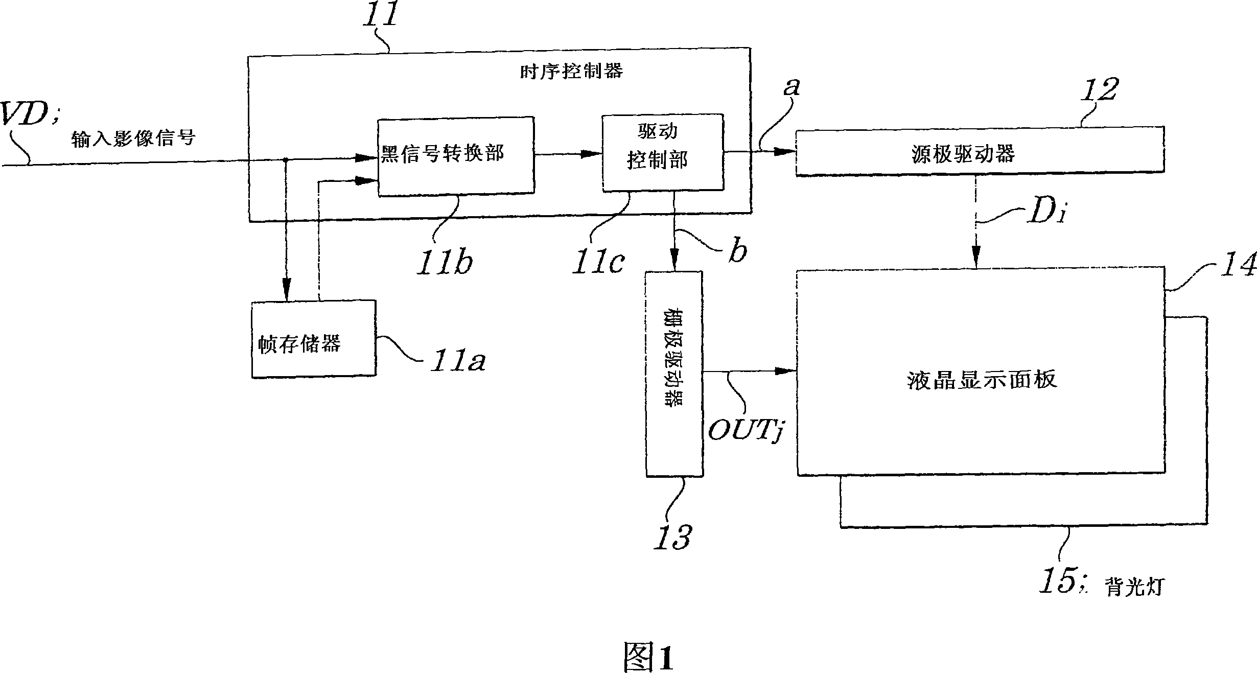
[0049] FIG. 1 is a block diagram showing the electrical configuration of main parts of a liquid crystal display device according to a first embodiment of the present invention. The liquid crystal display device in this example, as shown in FIG. 1 , includes a timing controller 11 , a source driver 12 , a gate driver 13 , a liquid crystal display panel 14 , and a backlight 15 .

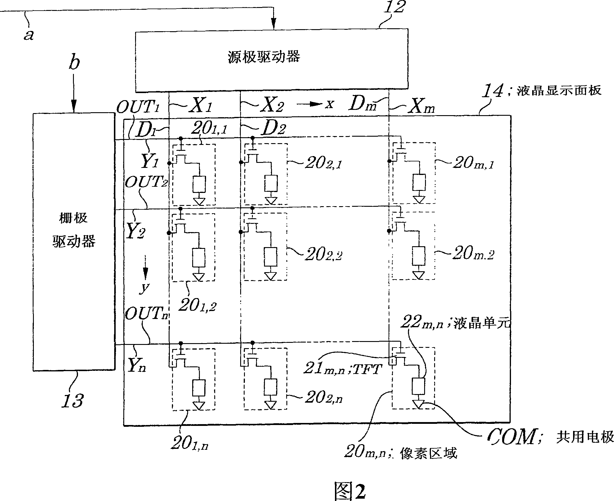
[0050] FIG. 2 is a schematic diagram showing an example of the electrical structure of the liquid crystal display panel 14 in FIG. 1 . This liquid crystal display panel 14 is a transmissive liquid crystal panel that makes the light of the backlight incident. As shown in FIG. ), multiple rows of scanning electrodes Yj (j=1, 2, . The data electrodes Xi are arranged at predetermined intervals in the x direction, and are applied with corresponding display data Di. The scan electrodes Yj are provided at predetermined intervals in the y direction perpendicular to the x direction, and are applied with a sca...

Embodiment 2

[0065] FIG. 11 is a timing chart illustrating the operation of the liquid crystal display device according to the second embodiment of the present invention. 12 is a diagram illustrating the voltage polarity inversion of data written in each pixel region of the second embodiment, FIG. 13 is a waveform diagram illustrating each part of the operation of each liquid crystal display device of the second embodiment, and FIG. 14 is A diagram of another example of voltage polarity inversion of write data written in the pixel region of the second embodiment. 15 is a diagram showing another example of voltage polarity inversion of write data written in a pixel region in the second embodiment. 16 is a diagram showing another example of voltage polarity inversion of write data written in the pixel region in the second embodiment. The processing contents of the driving method used in the liquid crystal display device in this example will be described with reference to the above-mentioned...

Embodiment 3

[0069] FIG. 17 is a timing chart illustrating the operation of the liquid crystal display device according to the third embodiment of the present invention. The above-mentioned embodiment 1 is driven at half the frequency of normal black insertion, but in embodiment 3, when the double-speed driving of the liquid crystal panel and each circuit is possible, 1 frame is divided into 4 fields, and the odd number When the switching frequency of the even-numbered field is set to a frequency more than twice the frame frequency, a liquid crystal display device, a drive control circuit and a driving method used in the liquid crystal display device can be provided, and the frequency multiplication caused by the high-speed frame frequency is related to the frequency multiplication of the liquid crystal display device. The frequency halving effect caused by the inventive drive cancels out, so the flickering frequency of black display and image display is doubled with the same operating freq...


PUM


Abstract

A liquid crystal display device is provided which is capable of improving quality of moving images. A field dividing driving operation is performed in which an odd field during which each of scanning electrodes in odd-numbered rows is sequentially driven and an even field during which each of scanning electrodes in even-numbered rows is sequentially driven occur, alternately and repeatedly, with time width of a refresh rate. In the former half of the odd field, display data is written in each of pixel regions corresponding to scanning electrodes in odd-numbered rows and, in the latter half of the odd field, black data is written in each of the pixel regions corresponding to scanning electrodes in the odd-numbered rows. In the former half of the even field, display data is written in each of pixel regions corresponding to scanning electrodes in the even-numbered rows and, in the latter half of the even field, black data is written in each of pixel regions corresponding to scanning electrodes in the even-numbered rows.

Description

technical field [0001] The invention relates to a liquid crystal display device, a driving control circuit and a driving method used in the liquid crystal display device, especially a liquid crystal display device suitable for displaying dynamic images, a driving control circuit and a driving method used in the liquid crystal display device. [0002] This application claims the priority of Japanese Patent Application No. 2006-101252 filed on March 31, 2006 and No. 2006-159001 filed on June 7, 2006, which are incorporated herein by reference. Background technique [0003] In recent years, liquid crystal display devices have been used not only as displays for personal computers but also for various displays such as liquid crystal televisions. In the case of being used in a TV, etc., the performance of displaying moving images is required. However, in the existing liquid crystal display device, when displaying moving images, the following image is displayed when the current ima...

Claims


Application Information

Patent Timeline
Patent Type & Authority Applications(China)
IPC IPC(8): G09G3/36G02F1/133H04N5/66
Inventor 木村裕昭
Owner NEC LCD TECH CORP
Why Eureka
Try Eureka