Method and device for detecting geometric figure of image

An image and technology to be detected, applied in image enhancement, image analysis, image data processing, etc.

Inactive Publication Date: 2008-01-23
PANASONIC CORP
View PDF2 Cites 32 Cited by
  • Summary
  • Abstract
  • Description
  • Claims
  • Application Information

AI Technical Summary

Problems solved by technology

However, the n-fold angle criterion adopted by this method is only suitable for regular polygon detection

Method used


Image

  • Method and device for detecting geometric figure of image
  • Method and device for detecting geometric figure of image
  • Method and device for detecting geometric figure of image

Examples


example 1

[0033] Example 1 (using the geometric relationship between inscribed circles)

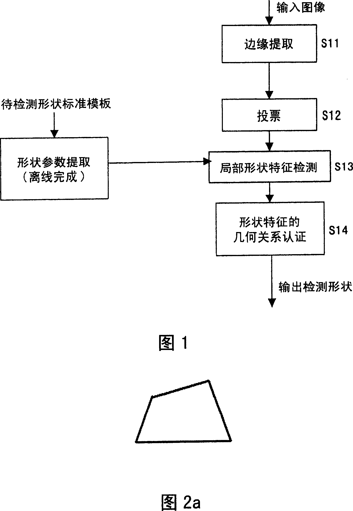
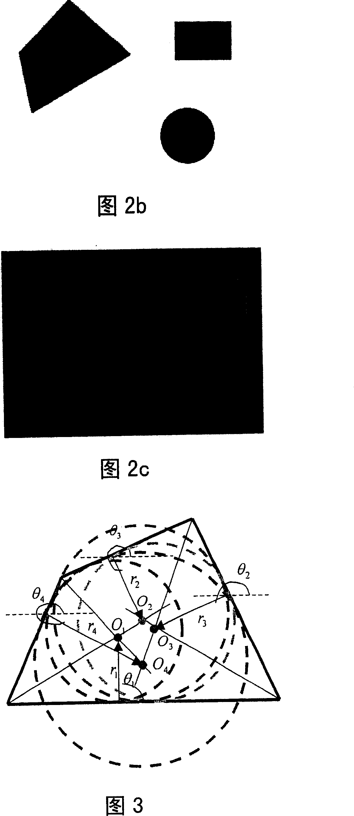
[0034] 2a to 2c show schematic diagrams of the basic process of polygon detection according to this example. Among them, Fig. 2a is a standard template of the shape to be detected; Fig. 2b is an input image, and Fig. 2c is an edge image representing the input image. Compared with the standard template shown in FIG. 2a, the shape to be detected contained in the image shown in FIG. 2b may have scale (zooming) and rotation transformations.

[0035] Edge extraction is to extract the parts with obvious grayscale (or color) changes from the input image, which correspond to the boundaries of objects. If the image is regarded as a two-dimensional function f(x, y), where (x, y) is the pixel coordinate of the image, and f is the grayscale (or color) value of the point, then the edge corresponds to the function f and changes quickly The point of , that is, the function gradientf=f x + f y The larger poin...

example 2

[0065] Example 2 (using the geometric relationship between the inscribed circle and the line segment)

[0066] Example 1 utilizes the geometric relationship among inscribed circles in the shape to be detected for shape inspection. In addition, the geometric relationship between the inscribed circle and the line segment can also be used for shape inspection. In this case, the inscribed circle determined by the combination of some line segments in the shape to be detected can be detected first, and then the existence of these line segments can be verified by using the geometric relationship between the inscribed circle and other line segments. The steps of this embodiment will be described below by taking the detection of the shape template shown in Figs. 11a and 11b as an example.

[0067] In the shape parameter extraction process, the arrow shape shown in Figure 11a is composed of several long and short line segments, for example, the long line segment l 1 l 5 , and the two...

example 3

[0077] Example 3 (using the geometric relationship between the inscribed circle and the curve segment)

[0078] The previous examples 1 and 2 are only for geometric shapes composed of straight line segments, and the present invention can also be applied to detect shapes containing both straight line segments (3 and above) and curved line segments. In this case, first detect the inscribed circle determined by the combination of straight line segments, and then use the geometric relationship between the inscribed circle and other curved segments to verify whether the curved segment exists. The specific implementation will be described below by taking the detection of the shape template shown in Figs. 13a and 13b as an example.

[0079] According to this embodiment, during the shape parameter extraction process, the shape parameter table of the template in Fig. 13a and 13b can be as shown in Table 3 (hereinafter referred to as the inscribed circle-curve segment table).

[0080] ...


PUM


Abstract

The invention provides a method for detecting a shape containing random line section combination, which comprises the following procedures: extract image edge from image and calculate the gradient direction of edge point; carry out voting operation for the calculated edge point to generate a voting image; detect the feature of partial shape to be detected via the voting image; compare the parameters about the shape feature with the shape parameters listed in the shape parameter form to determine the shape contained in the image. Therefore, the invention is able to automatically detect and recognize a plurality of shapes contained in image.

Description

technical field [0001] The invention relates to a method and device for detecting geometric shapes contained in digital images, which can be applied to technical fields related to shape detection, such as scene recognition in robot navigation, traffic sign recognition in automobile assisted driving, and remote sensing image analysis. Extraction of buildings in translation, etc. Background technique [0002] Shape detection is an important task in machine vision, the following are some existing methods: [0003] US Patent No. 3,069,654, entitled "A Method and Means for Recognizing Complex Patterns," issued to P.V.C. Hough in 1962, discloses a Hough transform method. This method utilizes the relationship between the image space and the parameter space, and determines the shape parameters in the parameter space by voting, which is robust to image noise interference and local shape information loss. But it is only suitable for shape detection with analytical expressions, and w...

Claims


Application Information

Patent Timeline
Patent Type & Authority Applications(China)
IPC IPC(8): G06K9/46G06T7/00G06V10/48
CPCG06T2207/30184G06T2207/30236G06T2207/30108G06K9/4633G06T7/0004G06T2207/10032G06V10/48
Inventor 吴刚刘伟杰谢晓辉魏强
Owner PANASONIC CORP
Why Eureka
Try Eureka