Plastic capillary pad, method and apparatus for producing the same

A capillary and plastic technology, which is applied in the field of manufacturing plastic capillary pads and equipment for manufacturing plastic capillary pads, can solve problems such as large assembly costs, tube connection damage, leakage, etc., and achieve good mechanical stress and strengthen the connection effect

Inactive Publication Date: 2008-07-16
BEKA HEIZ & KUEHLMATTEN
View PDF1 Cites 13 Cited by
  • Summary
  • Abstract
  • Description
  • Claims
  • Application Information

AI Technical Summary

Problems solved by technology

[0008] [08] The method of DE 197 25 326 C2 has the disadvantage that damage to the tube connection between the capillary and the collecting tube can

Method used


Image

  • Plastic capillary pad, method and apparatus for producing the same
  • Plastic capillary pad, method and apparatus for producing the same

Examples


Embodiment Construction

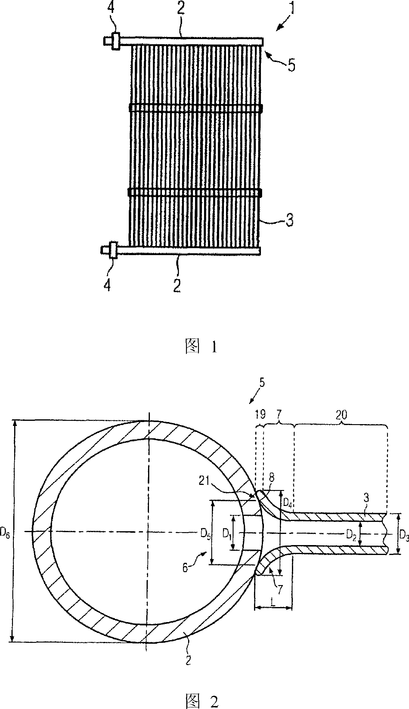
[0030] [30] First, the entire structure of the capillary pad 1 according to the present invention will be described with reference to FIG. 1.

[0031] [31] The capillary pad 1 includes two manifolds 2, which are connected by a plurality of parallel capillaries 3. The collecting pipe 2 has connection joints 4 at the ends respectively, and the collecting pipe can be connected to the heating fluid circuit and the cooling fluid circuit through the connection joints. When the capillary pad 1 is working, the heating fluid or the cooling fluid flows into one of the two manifolds 2. The heating fluid or the cooling fluid flows from the aforementioned manifold 2 through the capillary tube 3 to the other manifold 2. The heating fluid or cooling fluid flows from the second manifold 2 back into the heating fluid circuit and the cooling fluid circuit. The capillary pad 1 is installed, for example, in a ventilated ceiling of an indoor space. When the heating fluid or the cooling fluid flows thr...


PUM


Abstract

The invention relates to a method for producing a plastic capillary mat (1), in which a welding zone (19) at the axial end of a capillary (3) is radially welded to a manifold (2), wherein first Heating the weld zone (19) of the capillary (3) and the transition zone (7) adjacent to the weld zone (19) while increasing the outer diameter (D4) of the transition zone (7) and then removing the weld zone (19) Press onto the manifold (2). In order to improve the mechanical load-bearing properties of the capillary mat, the invention proposes to form a predetermined outer contour in the transition region ( 7 ) during the mutual pressing.

Description

Technical field [0001] [01] The present invention relates to a method for manufacturing a plastic capillary gasket, in which the welding zone of the axial end of the capillary is welded radially to the manifold, wherein the welding zone of the capillary and adjacent to the welding are first heated The transition zone of the zone, while increasing the outer diameter of the transition zone and then pressing the welding zone to the manifold. [0002] [02] In addition, the present invention relates to an apparatus for manufacturing a plastic capillary gasket, the apparatus includes: at least one heating device, by which the welding zone and the transition area of ​​the axial end of the capillary tube and the surrounding of the manifold are heated The area to be welded with a bifurcated opening; and a conveying device through which the welding area can be moved relative to the area to be welded. [0003] [03] In addition, the present invention relates to a plastic capillary gasket, the...

Claims


Application Information

Patent Timeline
IPC IPC(8): B29C69/00B29C57/02B29C57/04B29C65/02B29C65/78F28F9/18
CPCF24F5/0089B29B13/025B29C57/02B29C65/1432B29C65/20B29C65/72B29C65/7841B29C66/112B29C66/131B29C66/347B29C66/348B29C66/52241B29C66/7392B29C66/80B29C66/8122B29C66/81261B29C66/81419B29K2827/18B29K2995/0069B29L2031/18B29L2031/602F24F5/0092F28F9/187F28F21/063
Inventor 约瑟夫·克莱默阿耳布莱切特·鲍克雷纳德·索布柴克
Owner BEKA HEIZ & KUEHLMATTEN
Why Eureka
Try Eureka