Bar-shaped inductive component

Inactive Publication Date: 2018-11-29
INTICA SYST
View PDF3 Cites 1 Cited by
  • Summary
  • Abstract
  • Description
  • Claims
  • Application Information

AI Technical Summary

Benefits of technology

[0009]Preferably, the overlapping of the individual cores corresponds to at least half the area of the front of the individual cores, so that not only stability is achieved in a longitudinal direction, but also the necessary magnetic connection in the area of the overlap. A possible air gap between two consecutive individual cores is compensated by the resulting area of overlap.
[0010]In the area of the overlap, the in

Problems solved by technology

The gluing option improves the connection between the indiv

Method used


Image

  • Bar-shaped inductive component
  • Bar-shaped inductive component

Examples


Embodiment Construction

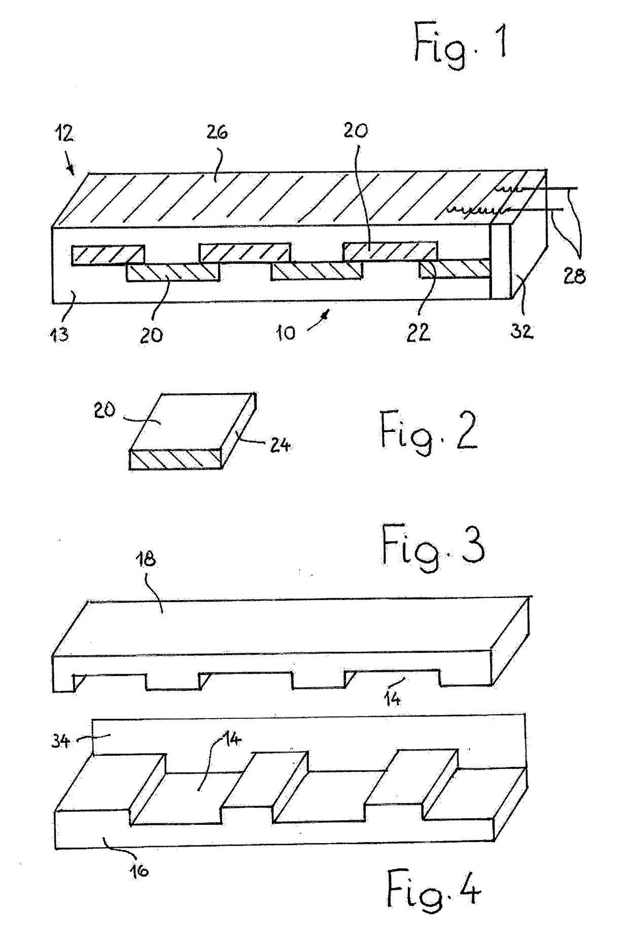
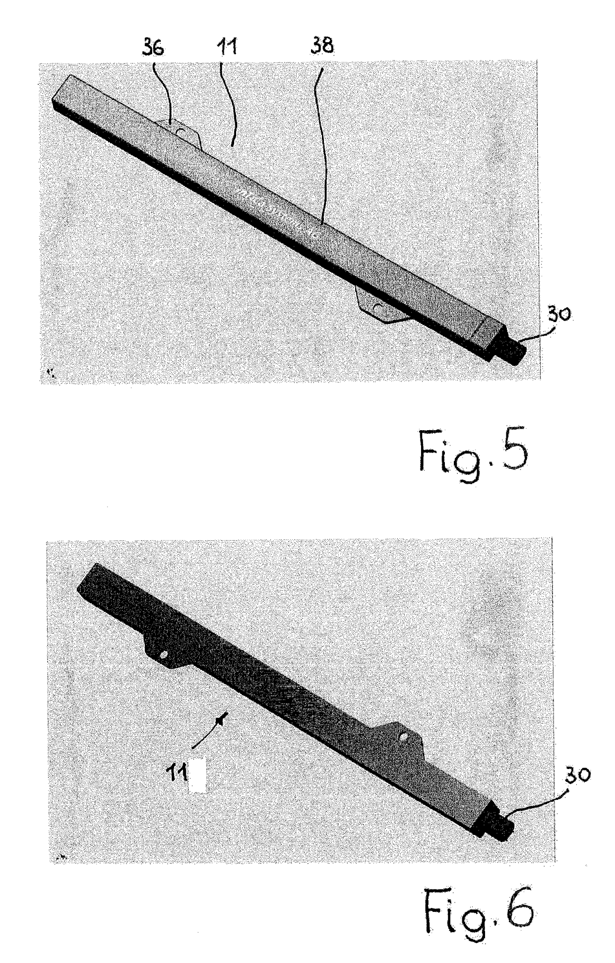
[0018]In FIGS. 1 and 2, as well as in FIGS. 3 and 4, schematic views of two alternatives for the possible construction of a bar-shaped inductive component 10 according to the invention are illustrated which, as shown in FIGS. 5 and 6, can be used as LF [low frequency] ferrite antennas 11 for frequency ranges from approx. 120 to 130 kHz or 14 to 25 kHz.

[0019]The inductive component 10 comprises a core made of magnetic material, in general ferrite, and a mounting element 12 for the core, which is formed as a coil body 13 and can be manufactured as a one-piece injection-moulded component, e.g. from polyamide (PA).

[0020]In the mounting element 12, cuboid recesses 14 are incorporated, which are closed on the not-shown rear side and extend over the width of the coil body 13, the length of which can be 100 mm or more. In the example shown in FIGS. 3 and 4, the coil body 13 is divided in a central plane and thus forms a bottom part 16 and a top part 18, both of which are firmly interconnect...


PUM


Abstract

The bar-shaped inductive component is made up of a core made from magnetic material and a mounting element for the core, which is divided into a series of individual cores. These are arranged and fixed relative to one another by means of the mounting element so that the ends adjoining one another overlap. At the same time, it is stipulated that the individual cores are offset relative to one another in at least two layers.

Description

BACKGROUND OF THE INVENTION[0001]The invention relates to a bar-shaped inductive component with a core made of magnetic material and a holding element for the core.[0002]Such inductive components are used, for example, as bar antennas with a ferrite core for contactless information and signal exchange and, when reinforced up to a length of 100 mm, in devices such as motor vehicles with keyless go systems. The objective of the OEM is also to keep the number of antennas as small as possible on cost grounds and, at the same time, to increase the automobile's ability to communicate with the access system in terms of range. By doubling the antenna length, a 100% increase in range is also achievable, whereas doubling the surface area leads only to about a 10% increase in range.[0003]Against this background, it is desirable to provide bar-shaped inductive components, in particular ferrite antennas with a length as great as possible, for example 300 mm. However, a problem remains in that co...

Claims


Application Information

Patent Timeline
IPC IPC(8): H01Q7/08H01F27/26H01Q1/32
CPCH01Q7/08H01F27/263H01Q1/3241H01F17/04H01F27/325H01F3/08
Inventor SICKLINGER, THOMASANETSEDER, THOMAS
Owner INTICA SYST
Why Eureka
Try Eureka