
Solar tile

Inactive Publication Date: 2014-03-27
XU ZHENGYUAN
View PDF1 Cites 2 Cited by
  • Summary
  • Abstract
  • Description
  • Claims
  • Application Information

AI Technical Summary

Benefits of technology

The sunlight tile described in this patent is designed to use solar energy to generate power and also cool down the tile and the part that converts solar energy. The technical effect of this invention is to provide a more efficient and effective way to generate energy from sunlight while also reducing the temperature of the components involved.

Problems solved by technology

However, upon application of BAPV technology, a supporting device used individually for supporting the solar cell panel is usually required, which increases costs and brings about trouble to installation.
The above situation limits the development of BAPV technology.
In addition, in order to better absorb sunlight, the solar cell panel in the solar tile is directly exposed to the sunlight during operation, and thermal radiation of the sunlight causes the temperature of the whole solar tile too high.
Due to action of heat conduction, the high temperature of the solar tile itself will affect its solar cell panel.
However, a too high temperature will bring side effects to the working efficiency of the polycrystalline silicon cell or monocrystalline silicon cell.
It can be seen that too high a temperature of the solar cell will adversely affect its converting efficiency and meanwhile quicken its attenuation speed and reduce its service life.
The above mode can carry away the heat produced by the sunlight tile frame due to sun thermal radiation, but it cannot eliminate the heat generated on the solar cell panel, including heat generated by solar energy thermal radiation on the cell panel and heat generated during photoelectrical conversion.
As such, the heat produced during photoelectrical conversion causes its surface temperature to rise, thereby affecting its converting efficiency.
Further, since about 80% of sunlight radiation is converted into heat of the solar cells and can not be further utilized, the coefficient of utilization to the solar energy in the current sunlight tile is then very low.

Method used


Image

  • Solar tile
  • Solar tile
  • Solar tile

Examples


first embodiment

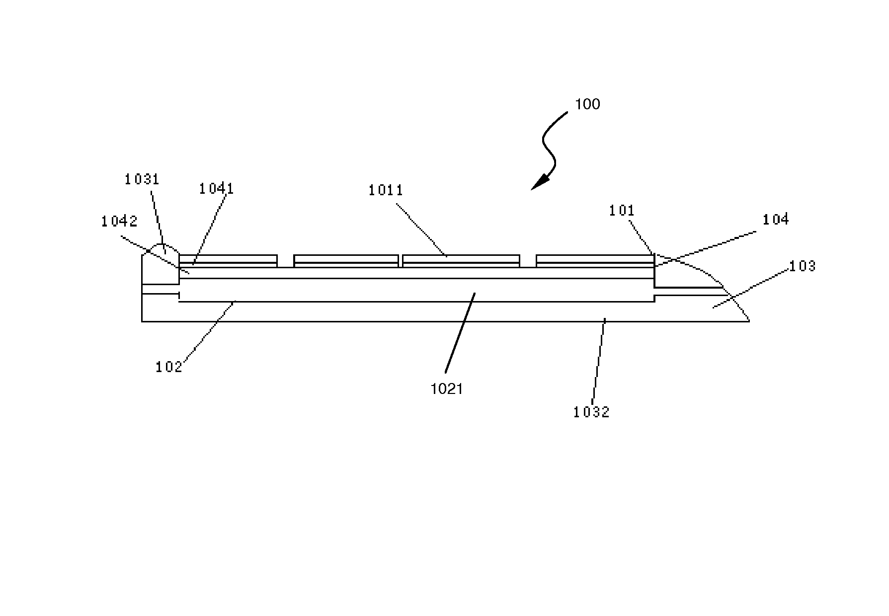
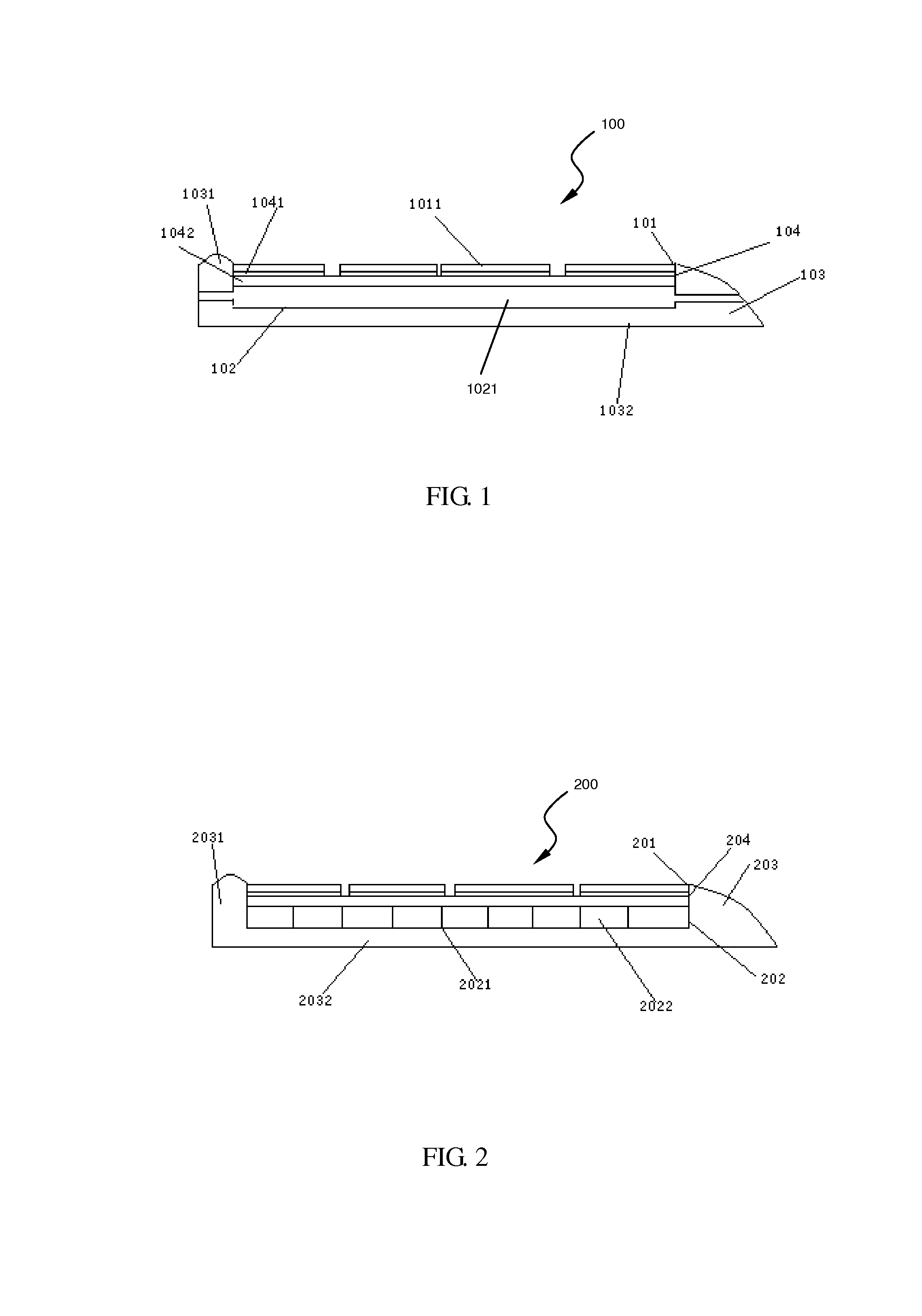
[0081]FIG. 1 shows a sunlight tile of the present invention. The sunlight tile 100 comprises: a solar energy converting unit 101, a cooling unit 102, an insulating heat conduction layer 104 and a tile body 103.

[0082]The tile body 103 can be integral and molded of a refractory flame-retardant unsaturated modified synthetic engineering plastic.

[0083]As shown in FIG. 1, the solar energy converting unit 101 is disposed on a surface of the tile and can be a single silicon cell or an array comprised of a plurality of silicon cells 1011, and a light permeable hydrophobic film layer (not shown) can be provided on a light receiving surface of the solar energy converting unit 101.

[0084]The insulating heat conduction layer 104 comprises a ceramic membrane layer 1041 and a metal heat conduction binding layer 1042, wherein the metal heat conduction binding layer 1042 can be formed of conductive silver paste. A backlighting surface of each silicon cell 1011 is applied to a screen printed metal he...

second embodiment

[0089]As shown in FIG. 2, in the present invention, the sunlight tile 200 comprises a solar energy converting unit 201, a heat absorbing assembly 202, an insulating heat conduction layer 204 and a tile body 203.

[0090]The sunlight tile in the second embodiment is substantially identical with the tile body in the first embodiment in structure, and the only thing is that the heat absorbing assembly 202 replaces the cooling unit 102 of the first embodiment. The heat absorbing assembly 202 is supported by the tile body 203 and disposed on a backlighting surface of the solar energy converting unit 201. As shown in FIG. 2, the heat absorbing assembly 202 can be an integrally formed groove plate 2021 which can be an aluminum substrate, so it has a good heat conduction performance.

[0091]In one embodiment of the present invention, the groove plate 2021 can be a transverse through groove which is wholly recessed, a thickness of the through groove is by far smaller than its length, and oil or w...

third embodiment

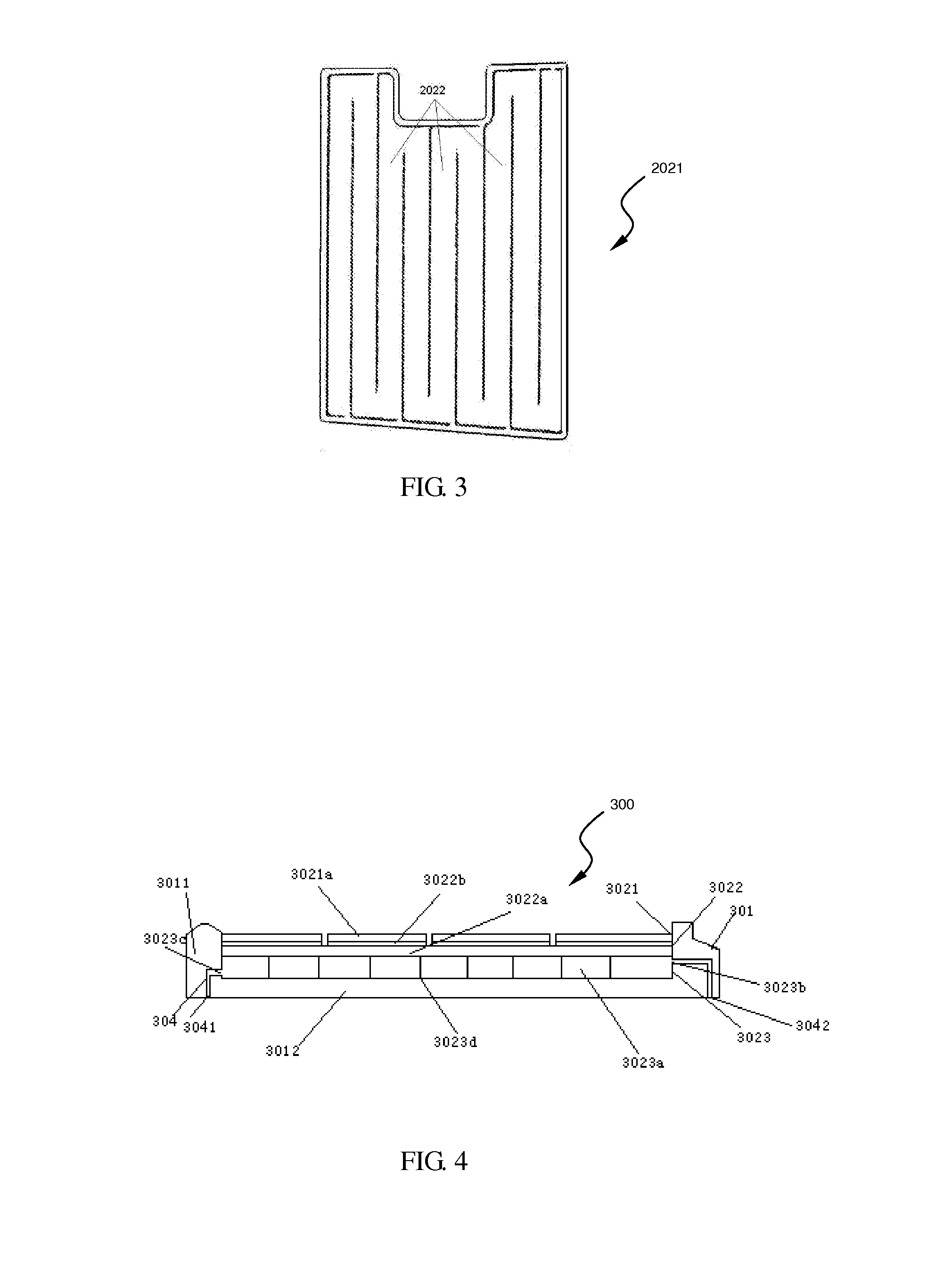
[0093]As shown in FIGS. 4-6, in the present invention, the sunlight tile 300 comprises a tile body 301, a solar energy converting assembly 302, an electrical output unit 303 and a heat transfer unit 304.

[0094]As shown in FIG. 4, the solar energy converting assembly 302 is supported by the tile body 301 and comprises a photovoltaic power generating unit 3021, an insulating heat conduction layer 3022 and a heat absorbing unit 3023.

[0095]As shown in FIGS. 5 and 7, the photovoltaic power generating unit 3021 is disposed on the surface of the tile body 301, and its light receiving surface may have a light permeable hydrophobic film layer (not shown). The photovoltaic power generating unit 3021 comprises a plurality of silicon cells 3021a which light receiving surface is a negative pole and which backlighting surface is a positive pole. The plurality of silicon cells 3021a are connected together in series. For example, as shown in FIG. 7, in an array with four columns and six lines of sil...


PUM


Abstract

The present invention relates to a photoelectrical and photo-thermal sunlight tile which has a waterproof performance as in ordinary tiles as well as a function of conducting photoelectrical and photo-thermal conversion. The sunlight tile comprises a solar energy converting assembly which converts light radiation of the solar energy into electrical energy and thermal energy and converts thermal radiation of the sunlight into thermal energy, whereby a utilization efficiency of the solar energy is substantially improved, a conversion loss rate is minimized and a conversion utilization rate is maximized.

Description

FIELD OF THE INVENTION[0001]The present invention relates to the field of building, particularly to an improvement to a tile, and more particularly to a tile having both photovoltaic power generating and photo-thermal processing function.BACKGROUND OF THE INVENTION[0002]Tiles are important roof waterproof materials, and are generally formed by baking clay or made of materials such as cement, and are shaped in an arch, planar or semi-cylindrical shape. In modern society, people are having higher and higher pursuit of comfortable building thermal environment so that energy consumption for building heating and air conditioning is increasing. In developed countries, energy used for building has already accounted for 30%-40% of a total energy consumption of the whole country, which imposes a certain restriction for economic development. Hence, people hope to apply solar energy technology to the building to lower energy used for the building. The tiles are usually laid on the top of a bui...

Claims


Application Information

Patent Timeline
IPC IPC(8): H01L31/048H01L31/058
CPCH01L31/058H01L31/0483Y02E10/44Y02B10/20Y02E10/60H02S20/25H02S40/44F24S10/72F24S2020/17F24S40/55F24S20/69Y02E10/50Y02B10/10
Inventor XU, ZHENGYUAN
Owner XU ZHENGYUAN
Learn More