Automated test tube cap removal apparatus

一种试管盖、盖帽的技术,应用在自动化试管盖帽移除装置领域,能够解决盖帽移除效率低等问题

Active Publication Date: 2008-07-23
IDS CO LTD
View PDF2 Cites 35 Cited by
  • Summary
  • Abstract
  • Description
  • Claims
  • Application Information

AI Technical Summary

Problems solved by technology

Therefore, the removal efficiency of the cap is very low

Method used


Image

  • Automated test tube cap removal apparatus
  • Automated test tube cap removal apparatus
  • Automated test tube cap removal apparatus

Examples


Embodiment Construction

[0033] Embodiments of the present invention will now be described with reference to the accompanying drawings.

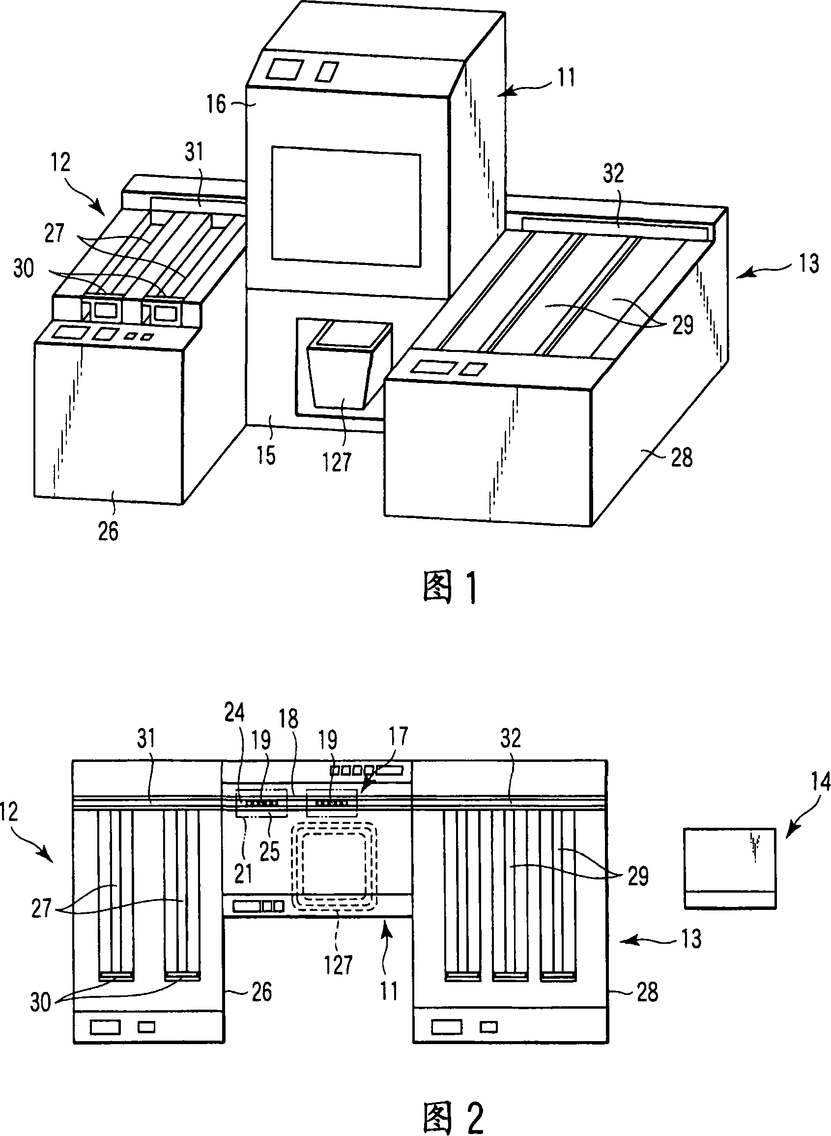
[0034] 1 and 2 are perspective and plan views, respectively, of an automated test tube cap removal apparatus. As shown in Figures 1 and 2, a cap remover 11 is provided in the central part of the device. An activation unit 12 serving as a test tube rack loading unit is provided on the left-hand side of the cap remover 11 , and a stacker unit 13 is on the right-hand side. Also, a control unit 14 having a CPU is provided near the starting unit 12 .

[0035] In the cap remover 11 , a storage box 16 is arranged on top of a base 15 , and a cap removing mechanism 17 (described later) is positioned in the box 16 . A rack transfer path 18 is provided at the rear of the box 16 . The transport path 18 transports a test tube rack 19 holding test tubes 20 .

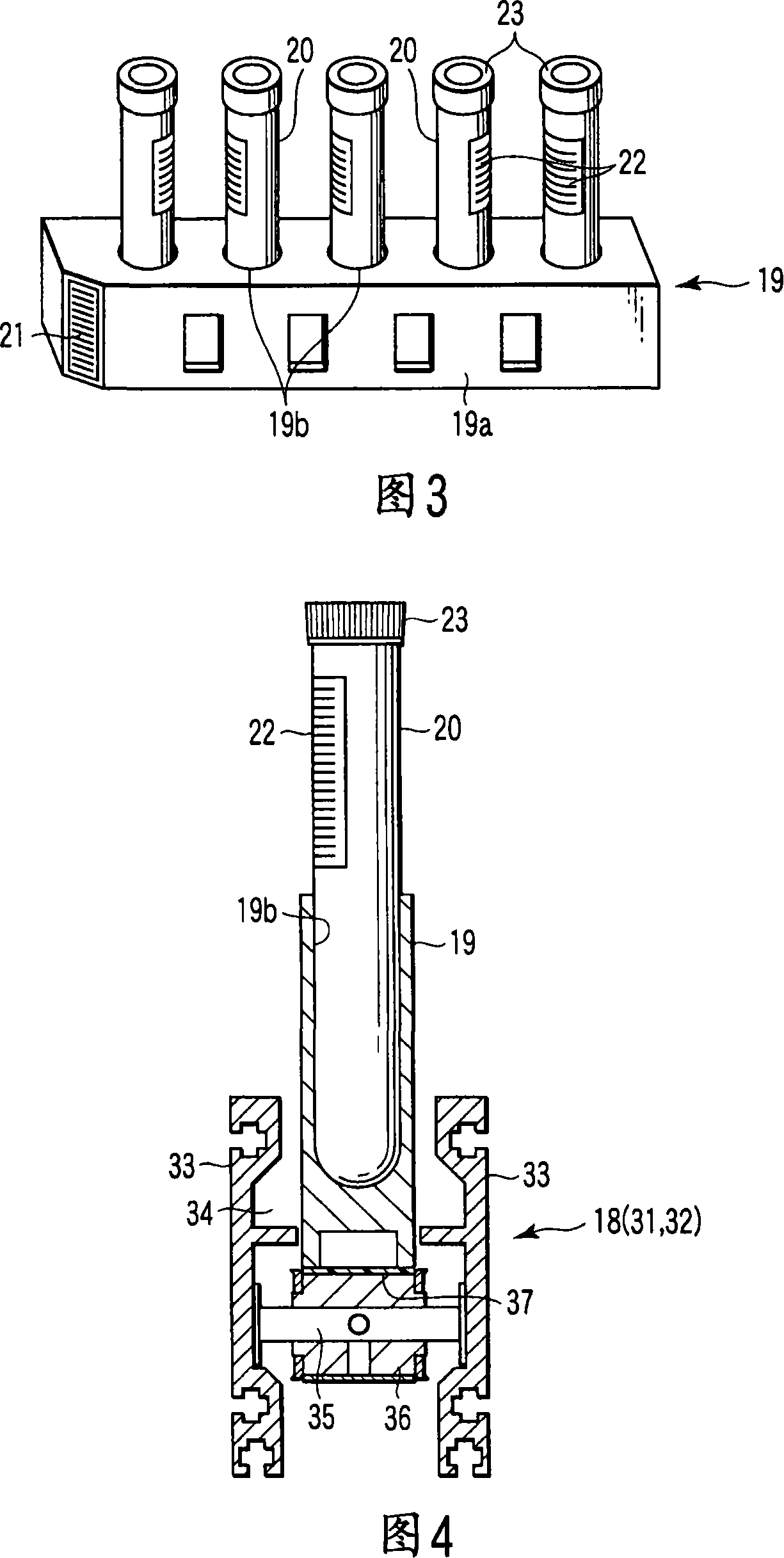
[0036] As shown in Figure 3, each test tube rack 19 can hold a plurality of test tubes 20, five test tubes in a row, ...


PUM


Abstract

A automated test tube cap removal apparatus includes: a cap remover (11) with a cap removing position (P1) for test tubes (20) contained sample; a test tube rack (19) which holds a plurality of capped test tubes (20) upright in a row, and loads to cap removing position (P1); a clamping mechanism (87) which is disposed in the cap removing position (P1) and clamps the plurality of test tubes (20); and a cap removal unit (112) disposed in the cap removing position (P1) and configured to move upward to remove caps (23) from some of a plurality of test tubes (20) and move upward to remove caps (23) from the remaining test tubes (20), and the caps (23) moves upward in meshing and supporting method for removing caps (23) from other test tubes (20). The cap removal unit includes engaging members (121), a lift mechanism (108), a cap guide member (117).

Description

technical field [0001] The present invention relates to an automated test tube cap removal device for automatically removing caps from test tubes containing samples such as blood. Background technique [0002] In a known device for removing caps from test tubes, for example as described in Japanese Patent Application Laid-Open No. 5-228379, the cap of each test tube is supported by engaging the distal end of the pull-out arm , in such a way that the test tubes are held in one-to-one correspondence by the test tube holders. Then, by actuating the lift cylinder with the cap supported by engagement, the pull-out arm is raised in the cap-pull-out direction to automatically pull the cap out of the test tube. [0003] The pull-out arm has a cap engaging pawl at its distal end and is configured to, together with the tilt guide, swing the arm supporting the cap around its axis through a predetermined angular range when the arm is pulled upward by the lift cylinder. [0004] Anothe...

Claims


Application Information

Patent Timeline
Patent Type & Authority Applications(China)
IPC IPC(8): G01N35/04B67B7/14B01L9/06B01L99/00B67B7/02G01N35/02
CPCG01N2035/041B67B7/02Y10T436/11Y10T436/114165Y10T436/113332G01N2035/0405B01L9/00B01L2300/042
Inventor 伊藤照明
Owner IDS CO LTD
Why Eureka
Try Eureka