
Method of measuring volumes of ink droplets and method of controlling nozzles of inkjet head using the method

一种喷墨头、喷墨打印头的技术,应用在仪器、印刷、光学等方向,能够解决差异等问题

Inactive Publication Date: 2008-11-12
SAMSUNG ELECTRO MECHANICS CO LTD
View PDF0 Cites 50 Cited by
  • Summary
  • Abstract
  • Description
  • Claims
  • Application Information

AI Technical Summary

Problems solved by technology

In a general imaging / printing process, this difference in volume might not be a serious problem, but it could be in more specialized areas of printing, such as color filter printing, where ink volumes must be precisely controlled

Method used


Image

  • Method of measuring volumes of ink droplets and method of controlling nozzles of inkjet head using the method
  • Method of measuring volumes of ink droplets and method of controlling nozzles of inkjet head using the method
  • Method of measuring volumes of ink droplets and method of controlling nozzles of inkjet head using the method

Examples


Embodiment Construction

[0031] Reference will now be made in detail to embodiments of the present invention, examples of which are illustrated in the accompanying drawings, wherein like reference numerals refer to like elements throughout. The embodiments are described below in order to explain the present invention by referring to the figures.

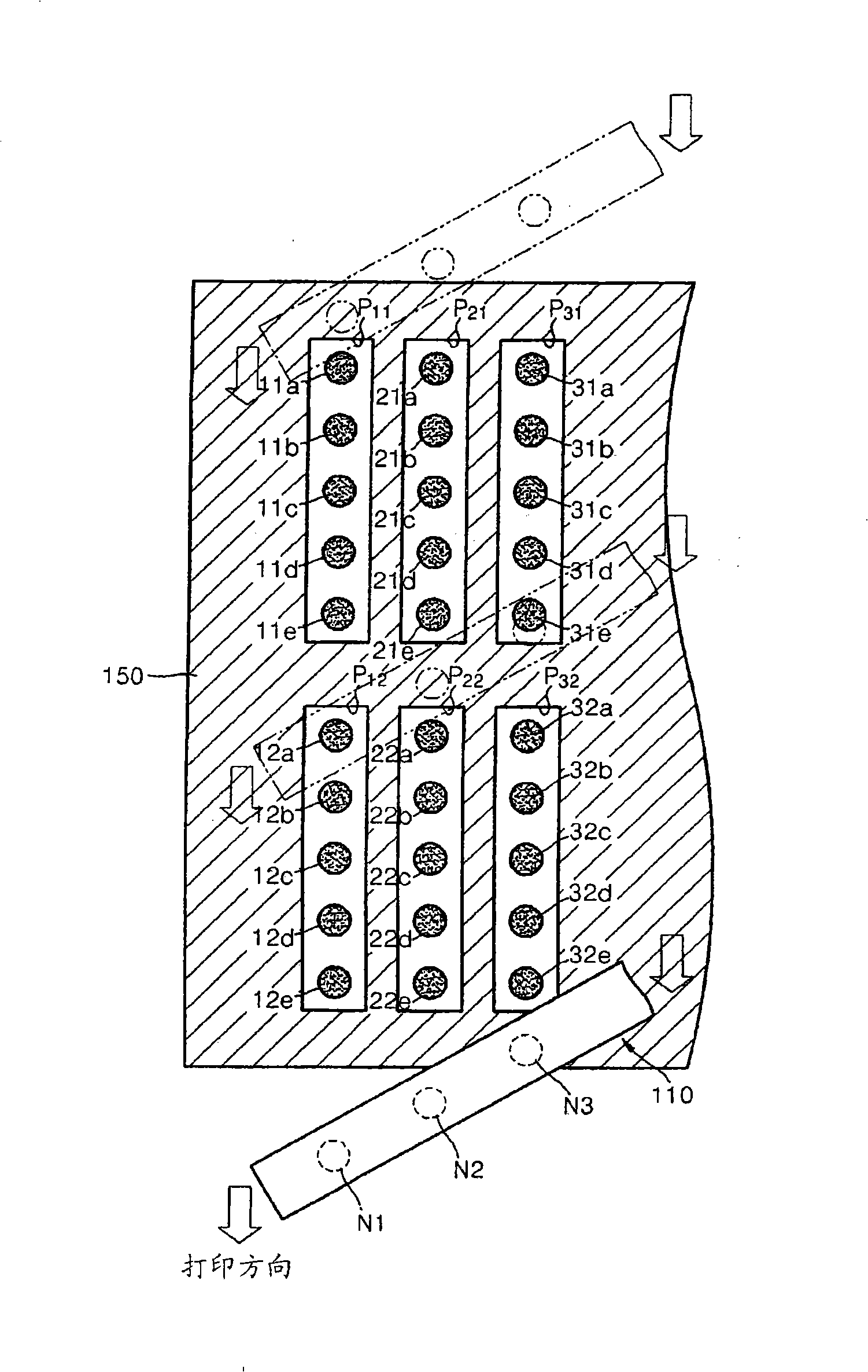
[0032] figure 2 The inkjet head 110 is shown for performing a printing process of printing in pixels to form color filters while moving in a printing direction and ejecting ink droplets.

[0033] refer to figure 2, a plurality of pixels P11, P12, P21, P22, P31, and P32 separated by the black matrix 150 are formed on a substrate (not shown) at predetermined intervals. Printing is performed by ejecting ink droplets from the nozzles N1 , N2 , and N3 of the inkjet head 110 into the pixels P11 , P12 , P21 , P22 , P31 , and P32 . exist figure 2 , since the pixel pitch (for example, the pitch between pixels P11 and P21 ) is narrower than the nozzle pitch (fo...


PUM


Abstract

A method of measuring the volumes of ink droplets is provided that includes repeatedly forming print patterns each including a plurality of ink droplets ejected from the inkjet head, photographing ink droplets which correspond to each other in terms of ejection order among the ink droplets of the repeatedly formed print patterns and measuring the volumes of the photographed ink droplets.

Description

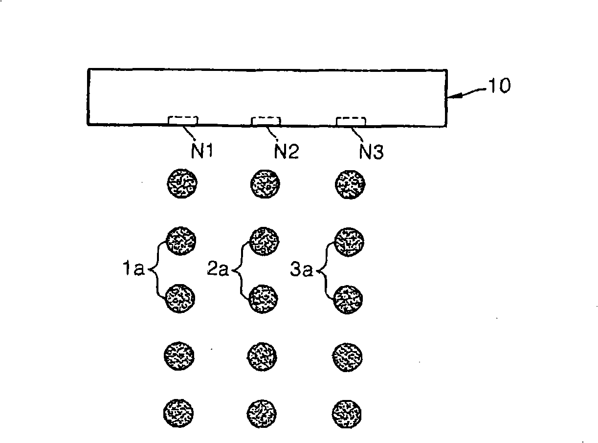
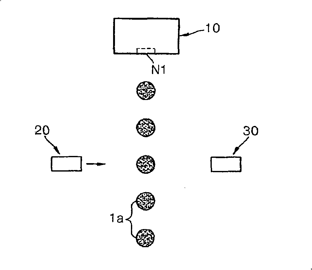
technical field [0001] The present invention relates to a method of measuring the volume of ink droplets ejected from nozzles of an inkjet head and a method of controlling the nozzles of the inkjet head using the method. Background technique [0002] In general, an inkjet head is a device that ejects ink droplets onto a desired position of a recording medium to form an image. Inkjet heads are classified into two types according to the inkjet mechanism. The first is a thermal inkjet head that ejects ink droplets by thermal energy due to the expansion force of air bubbles generated in ink. The other is a piezoelectric inkjet head that ejects ink droplets by pressure applied to ink due to deformation of a piezoelectric body. [0003] Recently, inkjet heads have been used in the imaging field and other fields. For example, inkjet heads have been used to manufacture color filters for liquid crystal displays (LCDs). Color filters have been manufactured by dyeing, pigment dispe...

Claims


Application Information

Patent Timeline
Patent Type & Authority Applications(China)
IPC IPC(8): B41J2/01B41J2/04B41J2/07
CPCB41J29/393B41J2/195B41J2/07B41J2/15G02F1/13
Inventor 金佑植金炳宪金相一
Owner SAMSUNG ELECTRO MECHANICS CO LTD
Learn More