Flow through cell and manufacturing method thereof

A manufacturing method and flow cell technology, which is applied in the field of flow cells, can solve problems such as leakage, easy leakage, gap between glass substrates and spacers, etc., and achieve the effects of improving adhesion strength, high reliability, and realizing high functionality

Inactive Publication Date: 2009-01-28
SHIMADZU SEISAKUSHO CO LTD
View PDF1 Cites 11 Cited by
  • Summary
  • Abstract
  • Description
  • Claims
  • Application Information

AI Technical Summary

Problems solved by technology

[0010]However, if the spacer is sandwiched between the glass substrates and only pressure is applied without adhesion, a gap will be generated between the glass substrate and the spacer
In particular, since the vicinity of the center is not pressurized, leakage tends to occur from the center
Easy to leak especially in the case of organic solvents

Method used


Image

  • Flow through cell and manufacturing method thereof
  • Flow through cell and manufacturing method thereof
  • Flow through cell and manufacturing method thereof

Examples


Embodiment Construction

[0042] Preferred embodiments of the present invention will be described below with reference to covering soil. In the examples, although an adhesive fluororesin was used as the fluororesin, a fluororesin other than the adhesive fluororesin may be used.

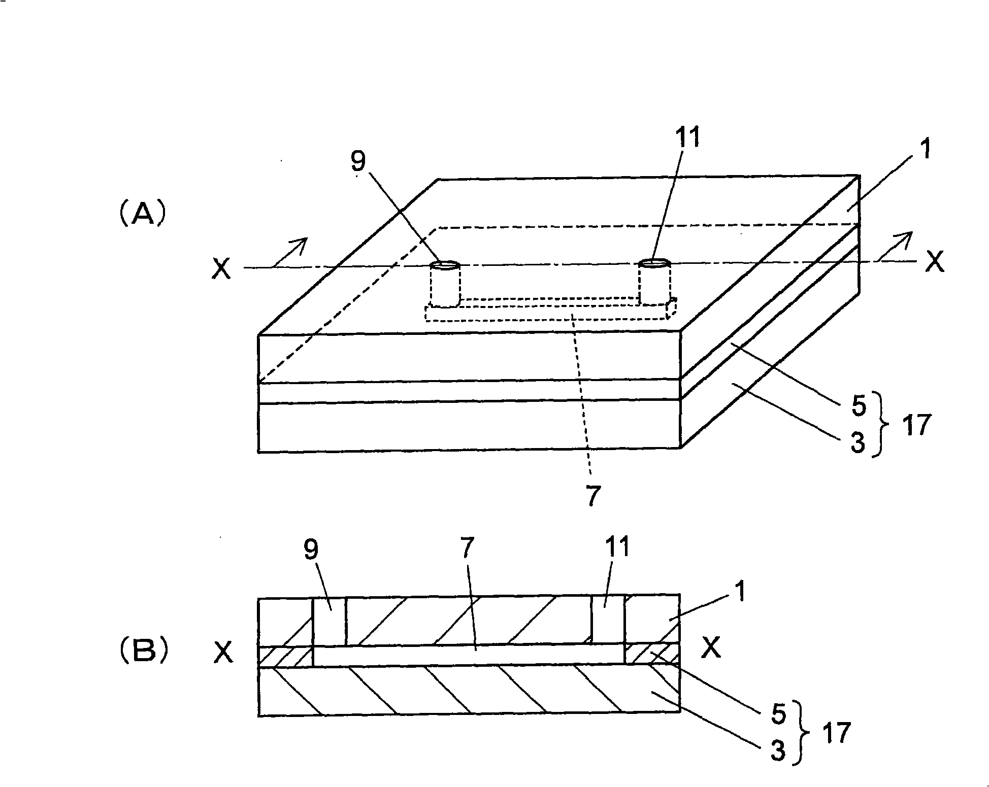
[0043] figure 1 It is a figure which shows the structure of the flow cell of one Example, (A) is a perspective view, (B) is a cross-sectional view taken along line X-X of (A).

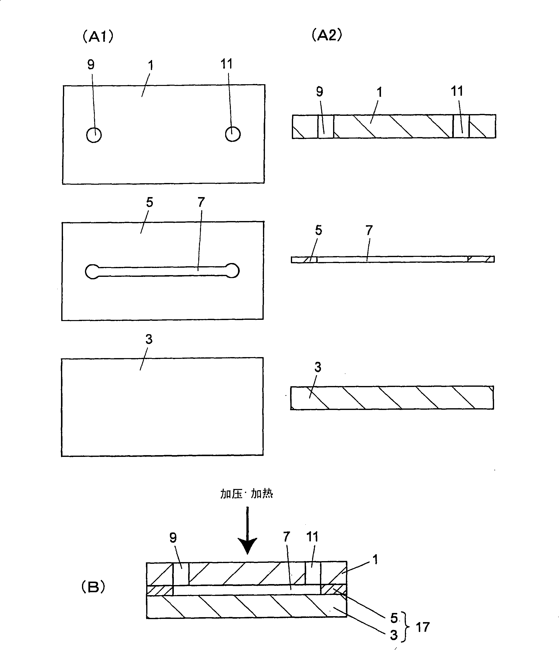
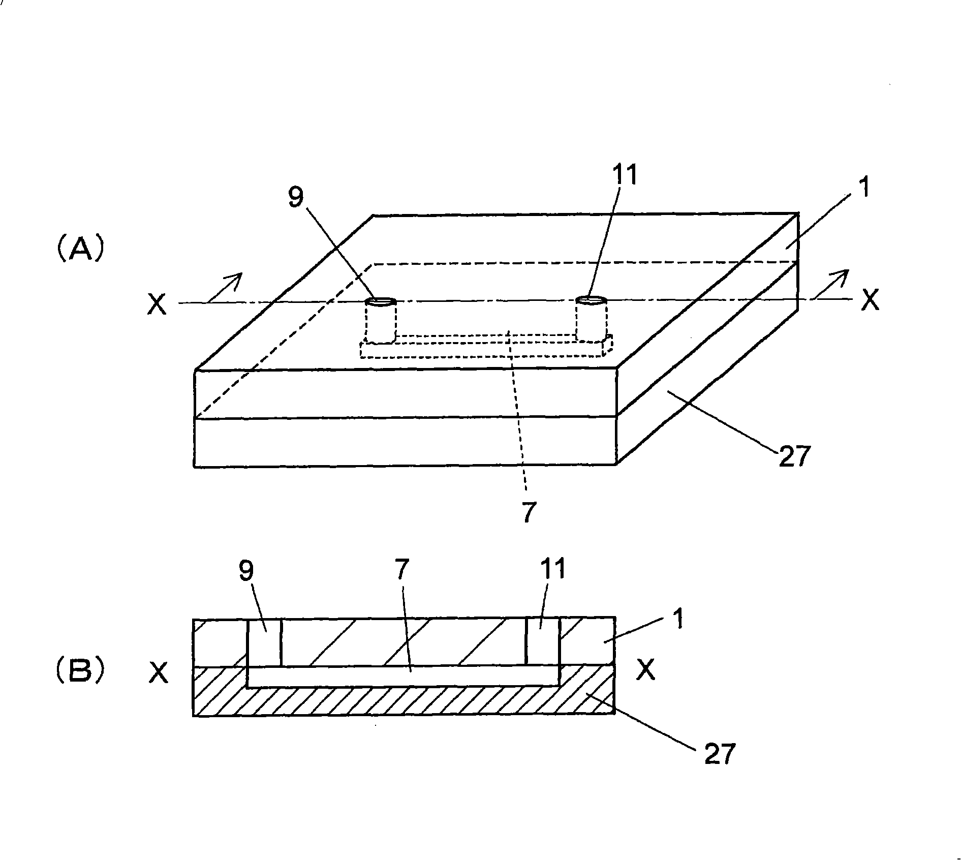
[0044]The flow cell of this embodiment is composed of a flat glass substrate 3, an adhesive fluororesin sheet 5 cut and processed with grooves serving as flow paths 7, and through holes for inlet or outlet of fluid formed at positions corresponding to both ends of the groove. The holes 9 and 11 are formed by the glass substrate 1 serving as a cover member, the fluororesin sheet 5 is sandwiched between the glass substrates 1 and 3, and the fluororesin sheet 5 itself is adhesively bonded. The flow path member 17 is constituted by the glass substrate 3 ...


PUM

PropertyMeasurementUnit
melting pointaaaaaaaaaa
decomposition temperatureaaaaaaaaaa
melting pointaaaaaaaaaa

Abstract

Provided is a flow cell that is free from liquid leakage and excels in chemical resistance. There is provided a preferred form of flow cell comprising flat-plate glass substrate (3); adherent fluororesin sheet (5) having a groove as flow channel (7) made by cutting machining; and glass substrate (1) as lid member furnished with through-holes (9,11) as fluid inlet and outlet at positions corresponding to both end portions of the groove. The fluororesin sheet (5) is interposed between the glass substrates (1,3) and, while heating at a temperature not lower than the melting point of the fluororesin sheet (5), pressurized so that the glass substrates (1,3) are bonded together by the fluororesin sheet (5) per se. Flow channel member (17) is constructed by the glass substrate (3) and, bonded thereonto, the fluororesin sheet (5).

Description

technical field [0001] The present invention relates to flow cells that can be used as flowmeters, conductivity meters, etc. for analytical instruments, as fluorescence detectors for liquid chromatography, and as microchips for electrophoretic separation, and their manufacturing methods Background technique [0002] In recent years, many flow cells capable of handling microfluids have been proposed by applying semiconductor manufacturing technologies such as etching methods such as microgroove processing. FIG. 7 shows an example of the structure of a conventional flow cell for handling microfluids. (A) is a perspective view, and (B) is a cross-sectional view at the X-X line position of (A). [0003] This flow cell is formed by laminating a plate-shaped member 34 formed with a groove serving as a flow path 7 on its surface and a plate-shaped member 32 formed with through-holes 9 and 11 at positions corresponding to both ends of the groove. [0004] Conventionally, as the pl...

Claims


Application Information

Patent Timeline
Patent Type & Authority Applications(China)
IPC IPC(8): G01N35/08G01N21/05G01N27/06G01N27/28G01N27/447G01N30/74G01N37/00
CPCG01N2021/0346B29K2027/12B29L2031/756B29C66/91411B29C66/91221B32B2038/047B29C66/91941B29C66/91931B01L2300/12B29C66/919G01N30/74B29C66/534B29C66/53461B29C65/5057G01N27/453B32B2457/00B29C65/4815B29C66/91214B01L2300/0887B29C66/91943B29C66/91933B01L3/502707B01L2200/0689B32B38/04G01N27/44721B01L2300/0816B29C66/91921G01N21/05B01L2300/0877B01L2200/147B29C66/91317B32B37/182B29C66/71Y10T156/10Y10T137/8593B29C66/1122
Inventor 叶井正树藤山阳一明地将一
Owner SHIMADZU SEISAKUSHO CO LTD
Why Eureka
Try Eureka