Ladle nozzle casting conduction plug and use method thereof

A technology for ladles and nozzles, which is applied in the field of drainage devices for casting molten steel in block nozzles, can solve the problems of large manpower, material resources and time, small coverage area, low strength, etc., and achieve improved drainage success rate, accurate setting position, and coverage area big effect

Inactive Publication Date: 2010-12-08
安徽中实冶金材料工程技术研究有限公司
View PDF1 Cites 3 Cited by
  • Summary
  • Abstract
  • Description
  • Claims
  • Application Information

AI Technical Summary

Problems solved by technology

Its disadvantages are: due to the bad operating environment such as deep ladle bottom, dark light, high temperature (nearly 1000°C), poor throwing accuracy, blind throwing, large amount of drainage agent, and long throwing time, especially for renovation and maintenance. During the process of transporting the steel ladle, the steel ladle vibrates and shakes. Before the drainage agent is thrown, the residues and sundries in the ladle will fall down one after another, and the gland will be on the nozzle and / or fall into the nozzle. The drainage agent cannot enter the nozzle, and the molten steel will be filled After the ladle, the nozzle is blocked; dealing with the nozzle blockage not only consumes a lot of manpower, material resources and time, but also affects production and is unsafe, and sometimes the drainage fails, causing the entire ladle of molten steel to be returned to the furnace, resulting in heavy losses
However, the disadvantages are that the drainage agent plug is slender, the amount of drainage is small, the coverage area is too small, the strength is low, and it cannot withstand the impact and heavy pressure of residues, and the nozzle is still easily covered or blocked, and its advantages are difficult to play.

Method used


Image

  • Ladle nozzle casting conduction plug and use method thereof
  • Ladle nozzle casting conduction plug and use method thereof
  • Ladle nozzle casting conduction plug and use method thereof

Examples


Embodiment 1

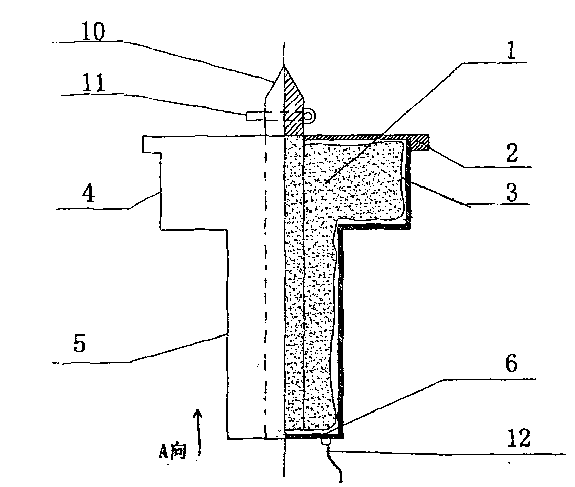
[0027] Depend on figure 1 , figure 2 It can be seen that the ladle nozzle casting drain plug is a circular cylindrical body with a variable diameter composed of the plug cap 4 , the plug cover 2 , the plug post 5 and the bottom plate 6 . Drainage agent is packed in soft bag 3, and soft bag 3 is placed in circular cylinder body, and soft bag 3 is heat-resistant 800-1000 ℃. The center of the plug cover 2 and the bottom plate 6 is provided with a guide rod hole 8, which is slidably matched with the guide rod 10, and the bottom plate 6 is provided with a ring buckle 7 to cooperate with the traction rope 12. There is a movable cover 9 next to the guide hole 8. When storing and transporting the drainage plug, close the movable cover to prevent the leakage of the drainage agent; when in use, the movable cover 9 is uncovered, and the guide rod 10 passes through the guide hole 8 and is slid on the drainage plug. middle. The guide rod 10 is also provided with a pin hole, and the rin...

Embodiment 2

[0029] Depend on image 3 , Figure 4 It can be seen that the ladle nozzle casting drain plug is a circular cylindrical body with a variable diameter composed of the plug cap 4 , the plug cover 2 , the plug post 5 and the bottom plate 6 . The drainage agent is filled in the circular cylinder, the center of the plug cover 2 and the bottom plate 6 is provided with a guide rod hole 8, which slides and fits with the guide rod 10, and the bottom plate 6 is provided with a ring buckle 7 to cooperate with the traction rope 12. There is a movable cover 9 next to the guide hole 8. When storing and transporting the drainage plug, close the movable cover to prevent the leakage of the drainage agent; when in use, the movable cover 9 is uncovered, and the guide rod 10 passes through the guide hole 8 and is slid on the drainage plug. middle. The guide rod 10 is also provided with a pin hole, and the ring pin 11 with a ring is inserted into the pin hole, and the traction rope 12 is hooked ...

Embodiment 3

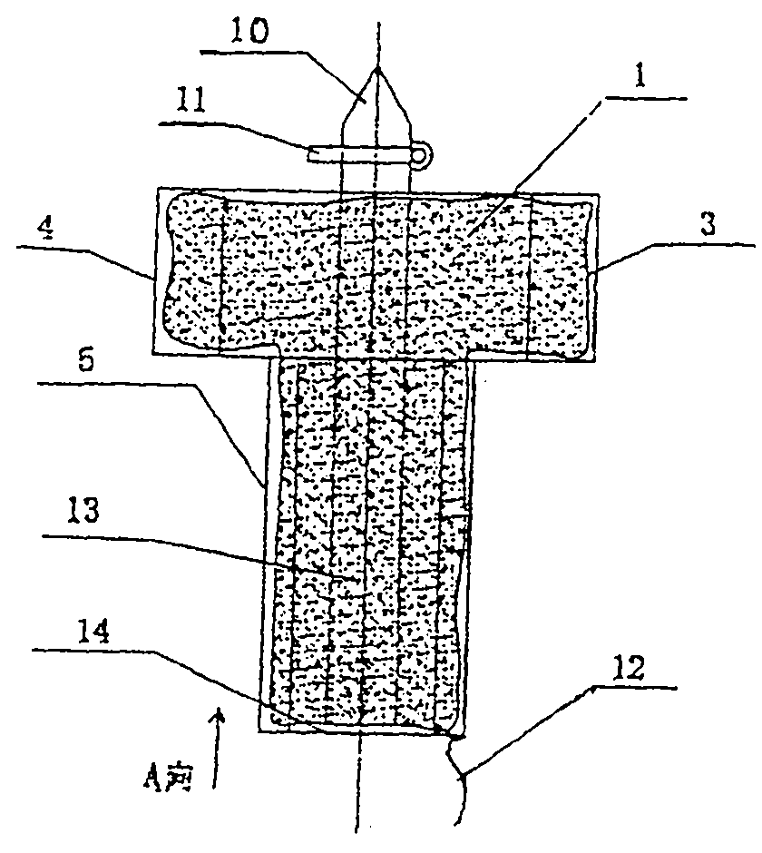
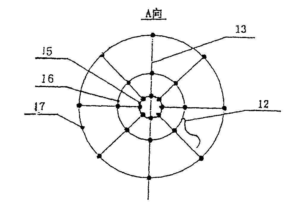
[0031] Depend on Figure 5 , Figure 6 It can be seen that the drainage plug is fixed by the bent iron wire 13 and the ring 14 to form a circular cage shape with reduced diameter, and the consolidation method can be welding or binding connection. Ring 14 contains three kinds of rings, small ring 15 is slidingly matched with guide rod 10, the upper and lower ends of plug cover 4 and plug post 5 are fixedly connected by small ring 15 and iron wire 13, and middle ring 16 is fixed with iron wire 13. Connect to form the plug post 5, the large ring 17 and the iron wire 13 are solidly formed into the plug cap 4, and the drainage agent 1 is packed into the metal mesh bag 3 and placed in a circular cage. The iron wire 13 and the circular ring 14 have a single bending shape and are easy to consolidate and form. When casting, they have a large contact area with molten steel and are easy to melt, which is more beneficial to drainage.


PUM


Abstract

The invention discloses a ladle nozzle casting drainage plug and a using method thereof. The invention belongs to an attachment device of the ladle for starting the casting operation, in particular to a drainage device used for casting molten steel by a brick cup nozzle at the bottom part of the ladle as well as a using method thereof. The drainage device includes a drainage agent and is characterized in that a plug cap and a plug post are connected into a cylinder with variable diameters; a plug cover is arranged on the plug cap; a bottom plate in a mushroom shape is arranged below the plug post; the drainage agent is packaged / or directly connected into the cylinder composed of the plug cap, the plug post, the plug cover and the bottom plate by a soft bag; the plug cap and the plug post are arranged in a guide rod in a sliding way; a haulage rope is hung on the bottom plate. When in use, the plug post is inserted and fixed into the brick cup nozzle; the plug cap is covered above the brick cup. During casting, the drainage agent drains under the effects of the heat and the gravity of the hot molten steel. The invention has the advantages of simple structure and easy manufacturing;being convenient for arranging the drainage plug for a short time; proper dosage of the drainage agent, high intensity, accurate position, large covering area, stable, safe and reliable mounting, avoiding residues from plugging the nozzle, saving the cost for treating the plugging of the nozzle and being beneficial to production.

Description

technical field [0001] The invention belongs to an accessory device for ladle starting casting operation, in particular to a drainage device for casting molten steel at a block nozzle at the bottom of the ladle and a method for using the same. Background technique [0002] Molten steel casting is an important process of steelmaking production. The smelted molten steel is cast directly through the ladle or after being refined. At present, most factories adopt the sliding nozzle to control the casting. In order to prevent the residue in the ladle from blocking the nozzle and ensure the smooth pouring of molten steel, before tapping, a special person is set up at the tapping point to throw the bagged drainage agent at the ladle nozzle for drainage. Its disadvantages are: due to the bad operating environment such as deep ladle bottom, dark light, high temperature (nearly 1000°C), poor throwing accuracy, blind throwing, large amount of drainage agent, and long throwing time, espe...

Claims


Application Information

Patent Timeline
Patent Type & Authority Patents(China)
IPC IPC(8): B22D41/18
Inventor 周宇明周宇辉
Owner 安徽中实冶金材料工程技术研究有限公司
Why Eureka
Try Eureka