LED light modulation apparatus suitable for controlled silicon dimmer

A dimming device and LED light source technology, which is applied to lighting devices, control/regulation systems, light sources, etc., can solve the problem that LED bulbs cannot be adjusted in brightness, and achieve the effects of simple structure, good dimming effect, and long service life

Inactive Publication Date: 2009-04-08
CIVILIGHT SHENZHEN SEMICON LIGHTING
View PDF0 Cites 20 Cited by
  • Summary
  • Abstract
  • Description
  • Claims
  • Application Information

AI Technical Summary

Problems solved by technology

Therefore, in the prior art, the thyristor dimmer cannot adjust the brightness of the LED bulb with built-in or external switching power supply.

Method used


Image

  • LED light modulation apparatus suitable for controlled silicon dimmer
  • LED light modulation apparatus suitable for controlled silicon dimmer
  • LED light modulation apparatus suitable for controlled silicon dimmer

Examples


Embodiment Construction

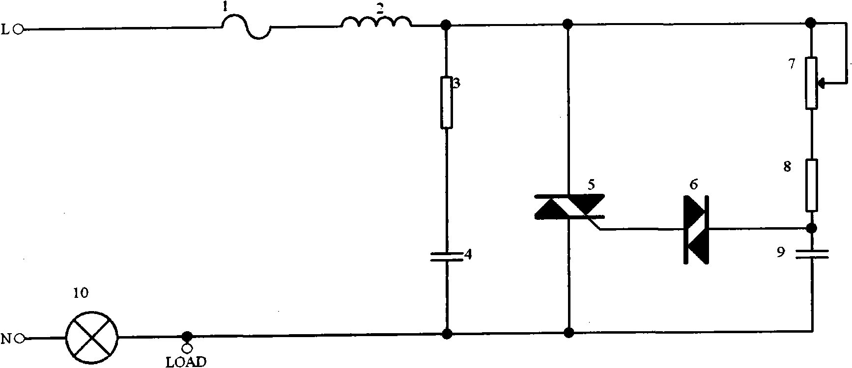
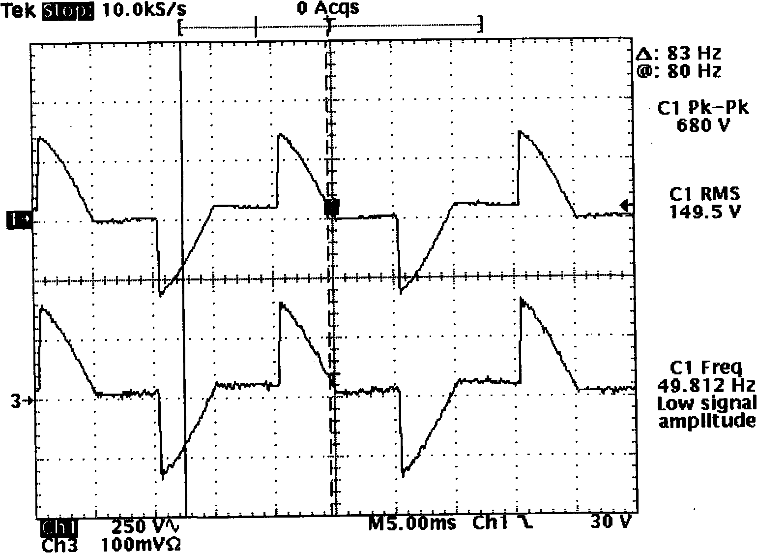
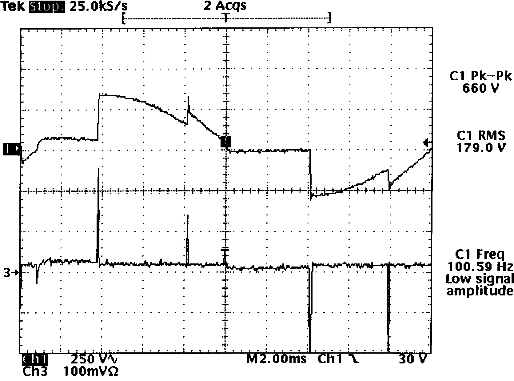
[0026] The specific embodiment of the present invention is: as figure 1 As shown in Figure 4, the voltage of the commercial power after phase-cutting by the thyristor dimmer is added to both ends of the input of the LED dimming power supply, and after being rectified into a DC voltage by the rectifier bridge 4, it is filtered by the electrolytic capacitor 21 through the diode 16. When the electrolytic capacitor 21 is fully charged, the voltage passes through the resistor 17 to start the MOSFET tube 15 to turn on, and the current flows from the dummy load resistor 14 to the MOSFET tube 15 to ground, forming a loop. Because the resistance value of the dummy load resistor 14 is small and close to the internal resistance of the tungsten bulb when it is working, the thyristor dimmer enters the normal phase-cutting working state (see Figure 6 ), and the voltage passes through the primary coil 33 of the high-frequency transformer to start the main power integrated block 38 and suppl...


PUM


Abstract

The invention relates to an LED dimming device which is applicable to a controllable silicon dimmer. The LED dimming device comprises a rectifier, a fictitious load circuit, a zero-crossing detection circuit, a high frequency transformer, a main power supply drive integrated circuit, a secondary rectification and filter circuit, a secondary power supply drive integrated circuit and an average voltage detection circuit. The invention has the beneficial effect that the LED dimming device is capable of realizing the brightness adjustment of an LED lamp by the controllable silicon dimmer and has the advantages of good dimming effect, long service life, simple structure and environmental protection and energy saving.

Description

technical field [0001] The invention relates to a dimming device, in particular to an LED dimming device suitable for a thyristor dimmer. Background technique [0002] In the prior art, the thyristor dimmer can adjust the brightness of the traditional tungsten bulb, see figure 1 , the conduction time of the thyristor dimmer 5 is determined by the charging time of the capacitor 9 of the circuit, thereby changing the conduction angle of the sine wave of the alternating current, changing the current of the tungsten bulb 10, and achieving the brightness adjustment effect , also known as cutting edge technology. Such as figure 1 As shown, the thyristor dimmer 5 is connected in series with the tungsten bulb 10. When the power is connected to the first moment, the current passes through the fuse 1, the inductor 2, the adjustable potentiometer 7, the resistor 8, the capacitor 9, and the tungsten bulb 10. , forming a charging circuit for charging capacitor 9, the charging time of ...

Claims


Application Information

Patent Timeline
Patent Type & Authority Applications(China)
IPC IPC(8): H05B37/02G05F1/10
Inventor 邹德志
Owner CIVILIGHT SHENZHEN SEMICON LIGHTING
Why Eureka
Try Eureka