
Portable self-supporting manual-lifting screen

A self-supporting, screen technology, applied in the direction of instruments, projection devices, optics, etc., can solve the problems of large tension of the folding support arm, falling of the upper support part, and inconvenient portability, etc., and achieves simple structure, good stability, good stretching, and durability. small force effect

Active Publication Date: 2011-05-25
GUANGZHOU GRANDVIEW CRYSTAL SCREEN CO LTD
View PDF1 Cites 0 Cited by
  • Summary
  • Abstract
  • Description
  • Claims
  • Application Information

AI Technical Summary

Problems solved by technology

Therefore, the strength required for the side arm is high, which increases the volume of the side arm and is not easy to carry
There is also a force-reinforcing part set between the lower side arm and the base part. When the screen is accommodated, the upper support part needs to be pressed hard. During the downward folding process, the force-reinforcing part and the connected lower side arm move toward the bottom in the same direction at the same time Lodging, when the angle between the force part and the bottom is less than 45 degrees, the upward supporting force will be lost due to the change of the force direction, but at this time it is difficult for the user to change the pressure to upward pulling force in time, and the upper supporting part will instantly fall and damage the screen
[0004] There is a problem with the folding elastic support arms used in the existing manual lifting screen, that is, during the screen storage process, the inner angle of the two support arms gradually decreases from about 120° to 0°, and at the same time the spring is gradually stretched to produce more and more tension. The stronger the pulling force, the greater the tension of the folding support arm, which will cause the central part of the pull-up rod to be locked in the center of the shell when it is fully stored, and one end of the arm is connected to the horizontal left and right ends of the pull-up rod. , the elastic force will make the two ends of the pull-up rod bounce and bend, causing damage to the screen

Method used


Image

  • Portable self-supporting manual-lifting screen
  • Portable self-supporting manual-lifting screen
  • Portable self-supporting manual-lifting screen

Examples


Embodiment Construction

[0046] The present invention will be further described below in conjunction with accompanying drawing.

[0047] The serial numbers of the parts in the accompanying drawings are as follows:

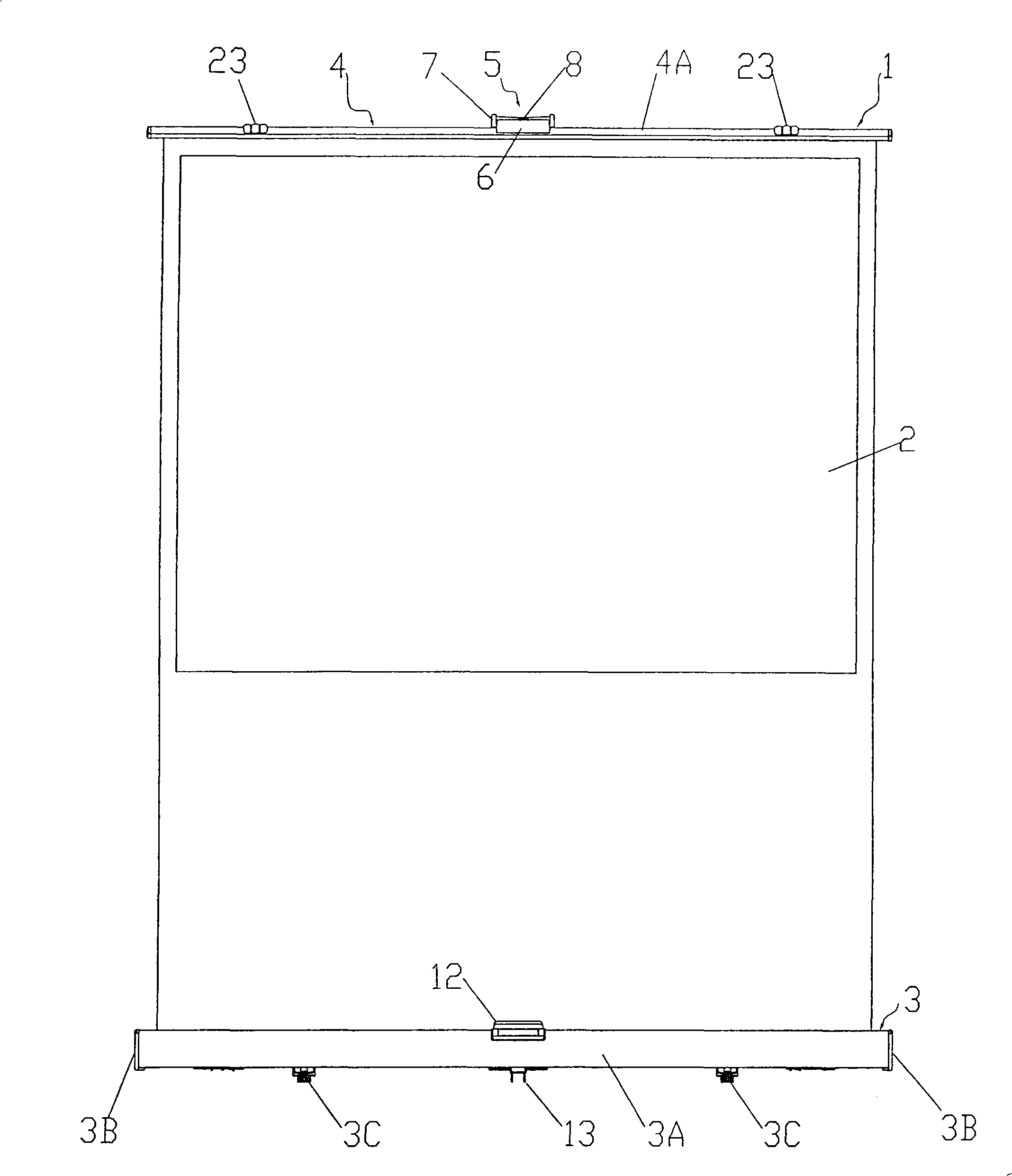
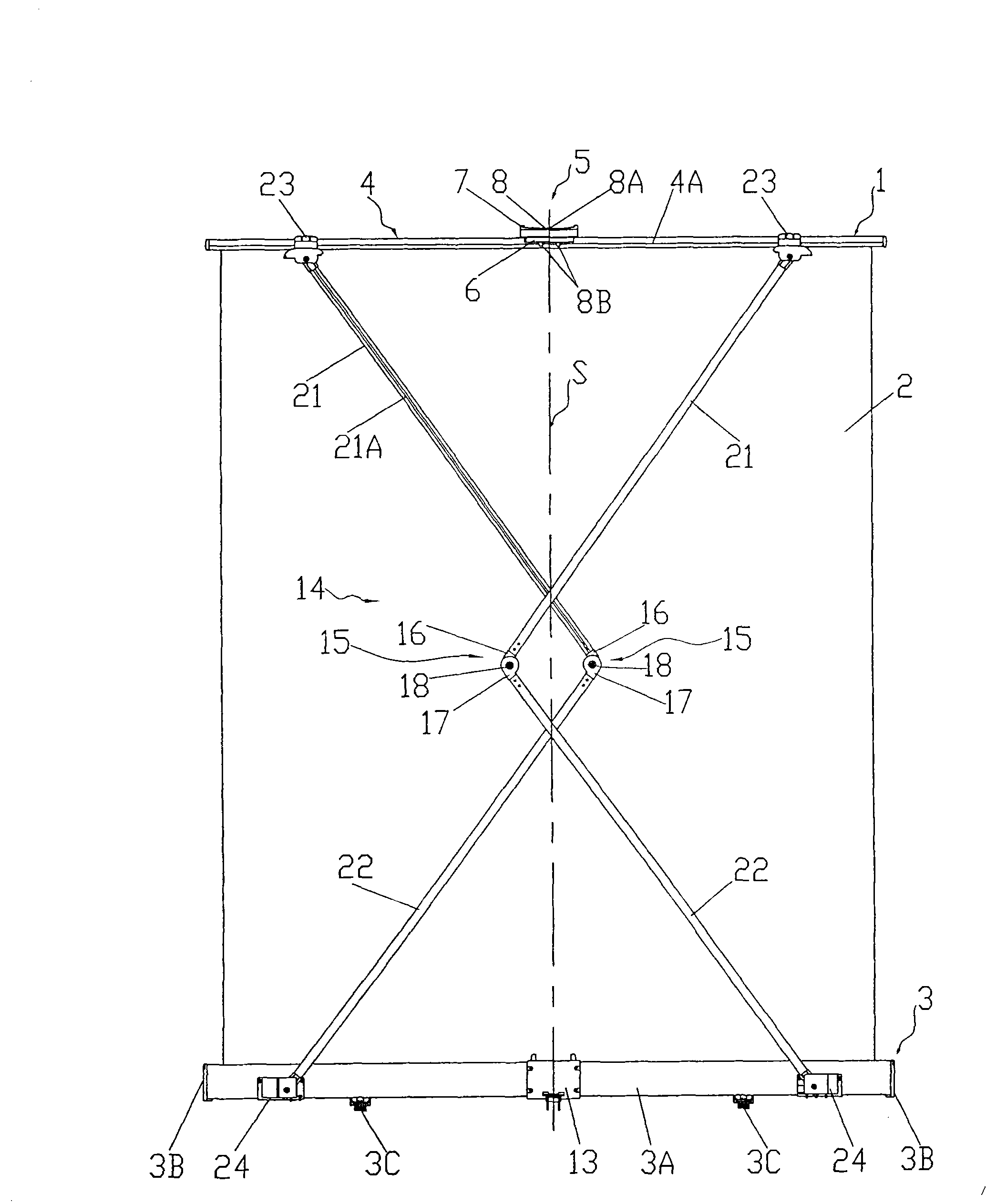
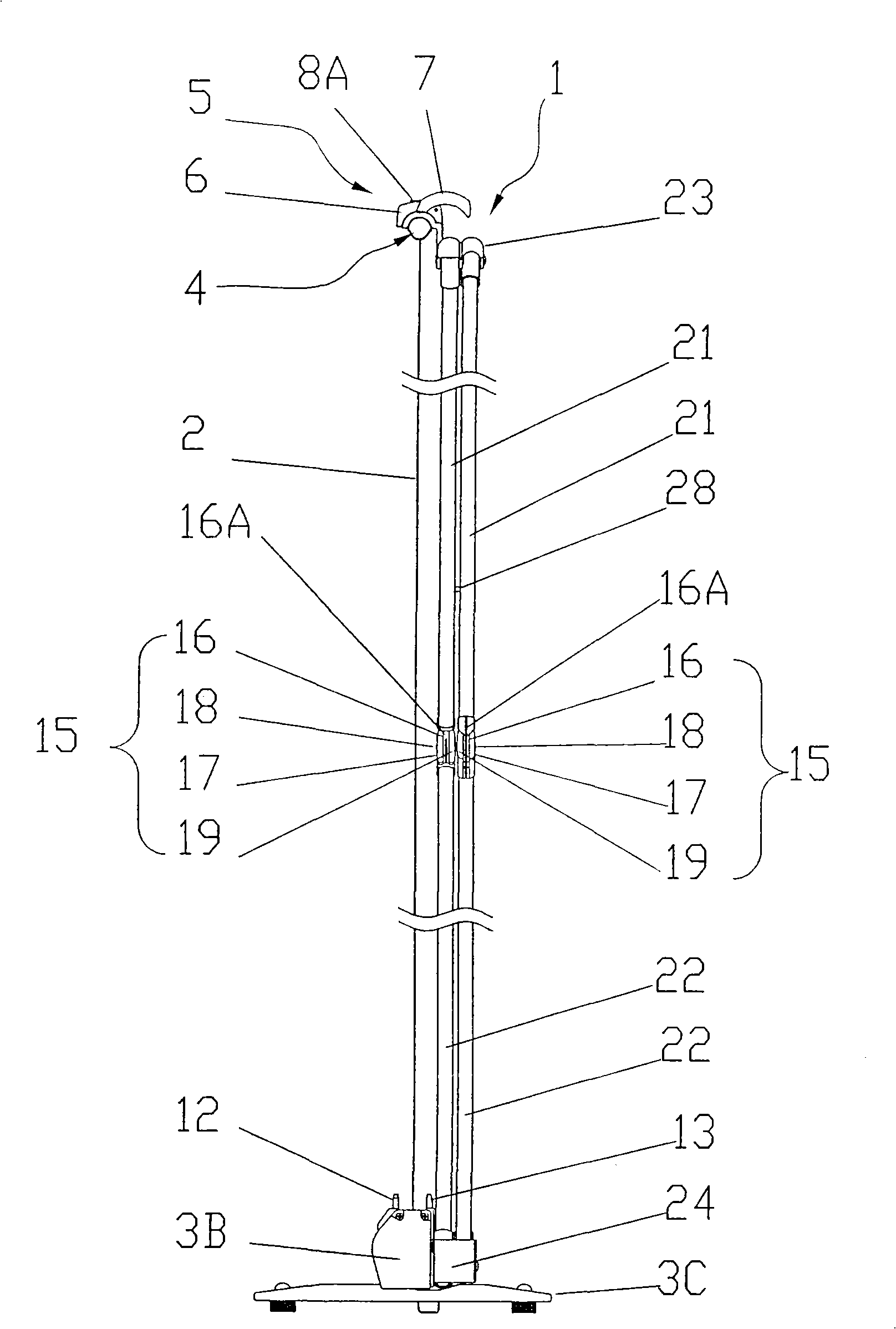
[0048] Lifting screen 1: Screen 2: Housing 3: Housing body 3A: End cap 3B: Foot 3C: Opening 3K; Upper rod support part 4; Upper rod 4A: Handle part 5: Handle cover 6: Square through hole 6A; spring baffle 6B: threaded part 6C: handle part 7: unlocking device 8: unlocking push key part 8A: engaging part 8B; sliding guide groove 8C: fixed frame 9: sliding guide post 9A; screw 10 : Return spring 11: Front base 12: Engaged portion 12A: Rear base 13: Engaged portion 13A: Supporting portion 13B; L-shaped folding support arm 14: Hinged connection portion 15: Upper hinged part 16 : U-shaped cable guide groove 16A: Deployed position limiting protrusion 16B: Lower hinge member 17: Cable guide groove 17A: Deployed position limiting support part 17B: Screw rod 18: Nut 19: Fixing piece at the upper en...


PUM


Abstract

The invention discloses a portable self-standing manual lifting screen which belongs to the field of screen devices or equipment used for projection or watching. The portable self-standing manual lifting screen is composed of a shell, an L-shaped foldable support arm, a screen, an upper pull rod, a drum and the like; the L-shaped foldable support arm is connected by hinging two support arms through a hinging part, a spring which can cause the L-shaped foldable support arm to fold and spring is arranged on the L-shaped foldable support arm, one end of the spring is connected with an upper support arm, the other end of the spring passes through the hinging part and is connected to a lower support arm, a tensile force guide groove is arranged on the hinging part to accommodate the spring, and the tensile force guide groove arranged on the hinging part consists of a deep groove and a shallow groove. The portable self-standing manual lifting screen has simple structure, convenient use and small volume, and is capable of meeting the unfolding height of the screen and is convenient for carrying; the support arms bear small force during folding the screen and can make long-time up and down movement of the screen without faults such as deformation, damage and the like.

Description

technical field [0001] The invention relates to a portable self-supporting manual lifting screen, which belongs to the field of screen devices or equipment for projection or viewing, and in particular relates to a portable self-standing manual lifting screen. Background technique [0002] There is an existing manual lifting screen, which is composed of lifting the handle part of the upper pull rod by hand to expand the screen upwards, or pressing down the handle part of the upper pull rod to curl the unfolded screen into the housing and lock it. Lifting the handle part to transport, for example, the structure is as follows, the left and right ends of the upper link member and the left and right ends of the bottom of the case are connected and supported by the left and right connection mechanism composed of the upper link side arm and the case bottom side arm, so that it can be stably The smooth expansion and contraction of the connecting mechanism and the smooth automatic er...

Claims


Application Information

Patent Timeline
Patent Type & Authority Patents(China)
IPC IPC(8): G03B21/58
Inventor 杨国强
Owner GUANGZHOU GRANDVIEW CRYSTAL SCREEN CO LTD
Learn More