Terminal apparatus, base station apparatus and communication system

A technology of wireless transmission and transmission antenna, which is applied in the directions of wireless communication, radio transmission system, space transmit diversity, etc., can solve the problem of not being able to fully obtain the multi-user diversity effect, etc., and achieve the effect of good multi-user diversity effect.

Active Publication Date: 2009-07-15
SNAPTRACK
View PDF1 Cites 0 Cited by
  • Summary
  • Abstract
  • Description
  • Claims
  • Application Information

AI Technical Summary

Problems solved by technology

[0013] The problem to be solved is that in the conventionally proposed communication system, the multi-user diversity effect cannot be sufficiently obtained depending on the allocated time slot and the position of the wireless receiver.

Method used


Image

  • Terminal apparatus, base station apparatus and communication system
  • Terminal apparatus, base station apparatus and communication system
  • Terminal apparatus, base station apparatus and communication system

Examples


Embodiment approach 1

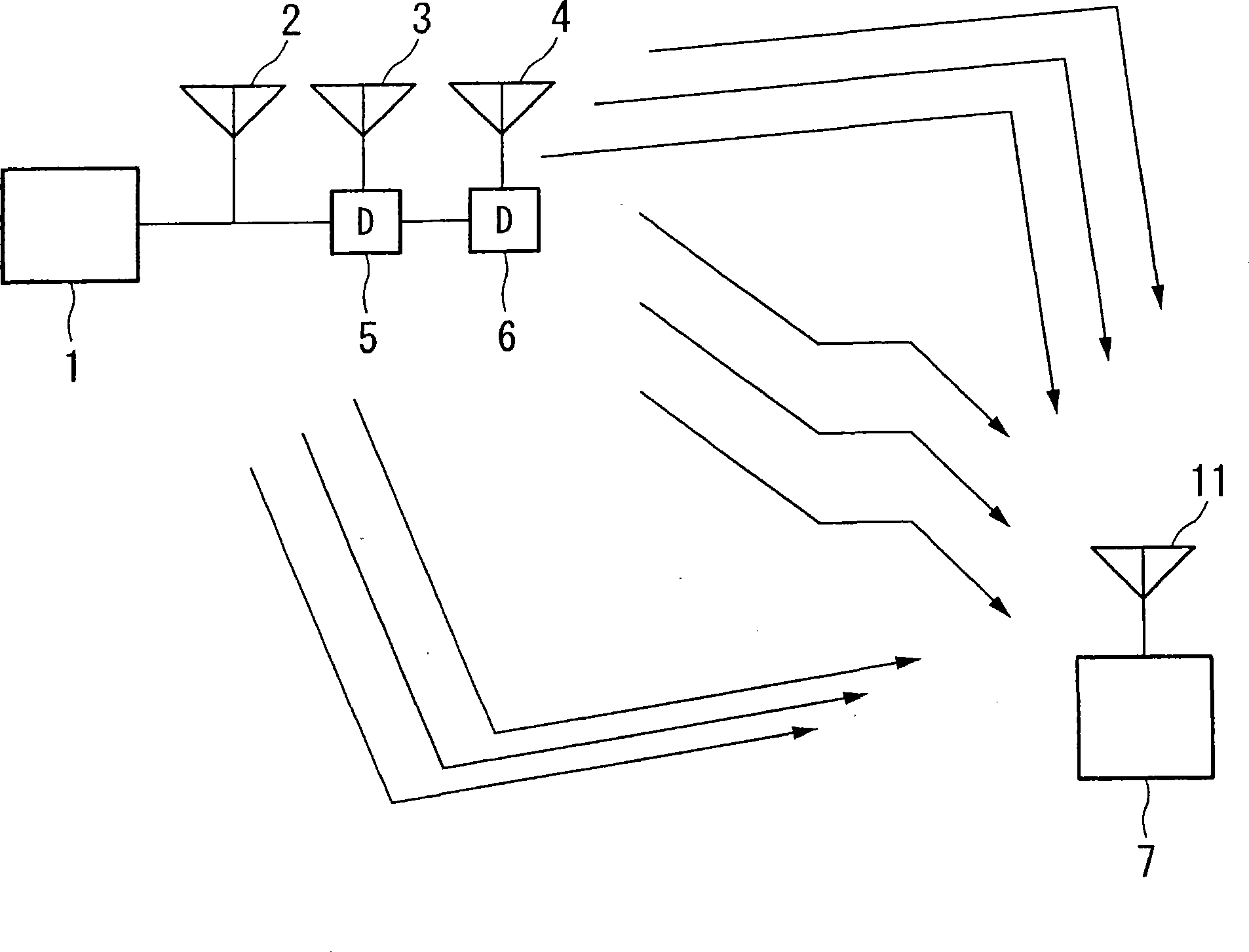
[0072] Next, a first embodiment of the present invention will be described with reference to the drawings. figure 1 It is a block diagram showing the configuration of the communication system in this embodiment. figure 1 A situation is shown in which a signal transmitted by the wireless transmitter 1 reaches the wireless receiver 7 via a plurality of propagation paths. The wireless transmitter 1 has a plurality of transmitting antennas 2 to 4, and gives different delay times 0, T, and 2T to each transmitting antenna, and transmits from each transmitting antenna 2 to 4. The wireless receiver 7 receives the signal transmitted from the wireless transmitter 1 . It should be pointed out that in figure 1 A case where the wireless transmitter 1 includes three transmitting antennas 2 to 4 is described as an example. It should be pointed out that the multiple transmitting antennas described here are used as an example, and the antennas mounted in the base station equipment such a...

no. 2 Embodiment approach

[0125] In this embodiment, a system will be described in which a terminal measures the amount of phase rotation for each antenna and notifies it to the base station. Figure 23 and Figure 10 roughly the same, but with Figure 10 The difference lies in the amount of phase rotation required to make the phase coincide with H1, that is, for the signal H2e from the antenna number 2 (transmitting antenna 3) jθ Additional phase rotation amount θ2 for signal H3e from antenna number 3 (transmitting antenna 4) j2θ By adding the phase rotation amount θ3, the reception signals from the three transmission antennas can be received in a state of in-phase addition in the terminal.

[0126] Figure 24 indicates the situation. That is, the transfer function after adding the delay of each antenna is H1, H2e jθ 、H3e j2θ . become these synthesized transfer functions namely H1+H2e jθ +H3e j2θ , but in the base station, the phase rotation of θ2 is added to the antenna of antenna number 2 (...


PUM


Abstract

The present invention provides a wireless transmitter comprising: a plurality of transmission antennas; a phase rotating unit which adds phase rotation to signals which are respectively input to the plurality of transmission antennas; and a reception unit which receives information on phase control of arbitrary antennas among the plurality of transmission antennas from another party of communication, wherein the rotating unit adds first phase rotation for controlling the maximum delay time between the plurality of transmission antennas and second phase rotation for controlling the phases of the arbitrary antennas among the plurality of transmission antennas based on the information.

Description

technical field [0001] The present invention relates to a wireless transmitter. [0002] The present invention claims the priority of Japanese Patent Application No. 2005-316549 filed in Japan on October 31, 2005, the contents of which are cited here. Background technique [0003] In recent years, a method of scheduling users mainly by dividing them into a plurality of blocks along the frequency axis-time axis in a multi-carrier transmission system has been proposed. It should be noted that, here, the area defined by the frequency axis and the time axis secured when the user communicates is called an allocated slot (slot), and the block that becomes the basis when the allocated slot is determined is called a block (chunk). [0004] Among them, it is proposed that in the case of transmitting broadcast / multicast channels and control channels, a wider block is allocated in the frequency direction to obtain the effect of frequency diversity, so that errors are less likely to o...

Claims


Application Information

Patent Timeline
Patent Type & Authority Applications(China)
IPC IPC(8): H04B7/06H04B7/12H04B1/707H04B7/02H04J11/00
CPCH04B7/0634H04B7/0842H04B7/12H04W48/16H04B7/0671H04B7/0673H04W24/00H04W88/08H04W48/20H04B7/0682H04W88/02
Inventor 今村公彦
Owner SNAPTRACK
Why Eureka
Try Eureka