
Optical fiber type mid-IR laser source generated by 3-5micrometre continuous wave differential frequency and its implementing method

An infrared laser and fiber-optic technology, applied in the optical field, can solve problems such as the difficulty in meeting the requirements of broadband tuning, the limitation of the spectral range of fiber amplifiers, and the wavelength tuning range of a single fiber laser is only tens of nanometers.

Inactive Publication Date: 2012-06-20
ANHUI INST OF OPTICS & FINE MECHANICS - CHINESE ACAD OF SCI
View PDF0 Cites 0 Cited by
  • Summary
  • Abstract
  • Description
  • Claims
  • Application Information

AI Technical Summary

Problems solved by technology

[0004] Although the wide gain spectrum characteristics of rare earth-doped glass fibers make it possible to realize broadband tuning of mid-infrared lasers in the 3-5 micron band, the wavelength tuning range of a single fiber laser is often only tens of nanometers due to the limitation of filter devices.
At the same time, the balanced output spectral range of the fiber amplifier is also limited, making it difficult to meet the broadband tuning requirements covering the 3-5 micron mid-infrared band

Method used


Image

  • Optical fiber type mid-IR laser source generated by 3-5micrometre continuous wave differential frequency and its implementing method
  • Optical fiber type mid-IR laser source generated by 3-5micrometre continuous wave differential frequency and its implementing method
  • Optical fiber type mid-IR laser source generated by 3-5micrometre continuous wave differential frequency and its implementing method

Examples


Embodiment Construction

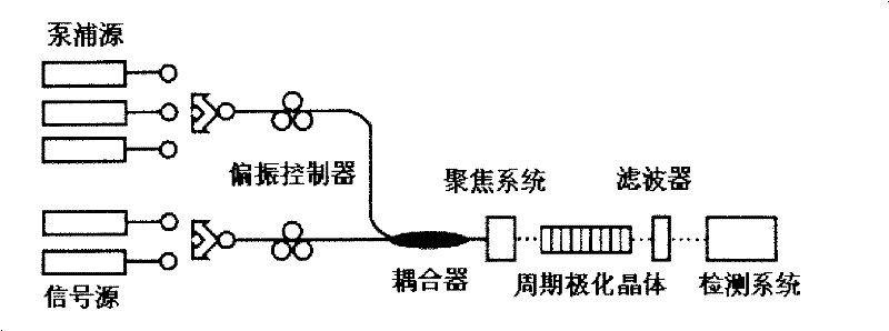
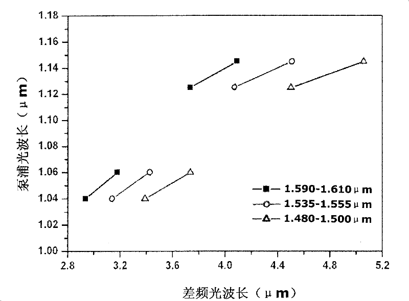
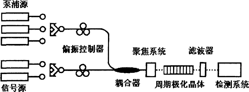
[0017] see figure 1 , the fiber-type 3-5 micron continuous wave difference frequency produces a mid-infrared laser source, the pump source and the signal source respectively adopt a wavelength segmentation combination scheme, which is characterized in that the signal source is composed of multiple bands of erbium-doped fiber lasers, and the bands are selected from S Waveband (1480-1530nm), C-band (1530-1560nm) and L-band (1565-1610nm); the pump source is also composed of multi-band ytterbium-doped fiber lasers, and the waveband is selected from 1000-1100nm and 1100-1200nm; The optical output ports of each of the erbium-doped fiber lasers are connected to the first output optical fiber, and the optical output ports of each erbium-doped fiber laser are connected to the second output optical fiber; the first and second output optical fibers are respectively connected with Polarization controller, the first and second output optical fibers are combined and coupled to a fiber coupl...


PUM


Abstract

The invention discloses an iraser light source in the generation of an optical fiber type 3-5-micron continuous wave difference frequency and a method for achieving the same, wherein a pump light and a signal light adopt a wavelength sectional combining plan, a rare-earth-doped fiber laser with suitable wavelength is selected, a pump source adopts a ytterbium-doped fiber laser with a wave band of1,060 nm and wave bands of over 1,100 nm, and the wave bands can be exchanged with each other. The signal light adopts an erbium-doped fiber laser with an S wave band, a C wave band and an L wave band, and the wave bands can be exchanged with each other. The ytterbium-doped fiber laser and the erbium-doped fiber laser emit the pump light and the signal light respectively, the pump light and the signal light are adjusted to be parallel with an optical axis of a crystal by a polarization controller respectively and are combined together by a fiber coupler, then a lens focusing system focuses the two light beams into a periodical polarization lithium niobate crystal; and by adjusting the length of the polarization cycle and the crystal temperature of the periodical polarization lithium niobate crystal, the pump light, the signal light and the difference frequency light meet a phase matching condition to finally achieve the infrared output in the generation of the difference frequency.

Description

technical field [0001] The invention relates to the field of optical technology, in particular to a mid-infrared laser light source generated by fiber-type segmented combination of 3-5 micron continuous wave difference frequency and its realization method. Background technique [0002] The baseband absorption of a large number of gas molecules is in the mid-infrared band, and the absorption intensity is 2-3 orders of magnitude larger than that in the near-infrared band, and it is mainly the vibration and rotation spectra of molecules, and the spectral lines are very dense. Therefore, using a mid-infrared band light source can achieve high Sensitivity detection and analysis. The mid-infrared laser light source based on difference frequency generation (DFG) technology inputs the pump laser and signal laser in the near-infrared band to the nonlinear crystal, and uses its second-order nonlinear effect to achieve pumping through phase matching. The difference frequency between t...

Claims


Application Information

Patent Timeline
Patent Type & Authority Patents(China)
IPC IPC(8): G02F1/39G02F1/377
Inventor 毛庆和蒋建常建华
Owner ANHUI INST OF OPTICS & FINE MECHANICS - CHINESE ACAD OF SCI
Learn More