Slant push device and method for pushing off products of stacking machine

A stacker and product technology, which is applied in the field of stacker product pushing device, can solve the problem of not being suitable for the high-speed operation of the stacker

Active Publication Date: 2009-08-19
ZHEJIANG YONGCHUANG MACHINERY
View PDF1 Cites 2 Cited by
  • Summary
  • Abstract
  • Description
  • Claims
  • Application Information

AI Technical Summary

Problems solved by technology

The objective existence is that the push-out mechanism in the stacker is not suitable for the high-speed operation of the stacker, and the stack-out mechanism needs two mutually perpendicular movements to synthesize, requiring two power sources

Method used


Image

  • Slant push device and method for pushing off products of stacking machine
  • Slant push device and method for pushing off products of stacking machine
  • Slant push device and method for pushing off products of stacking machine

Examples


Embodiment 1

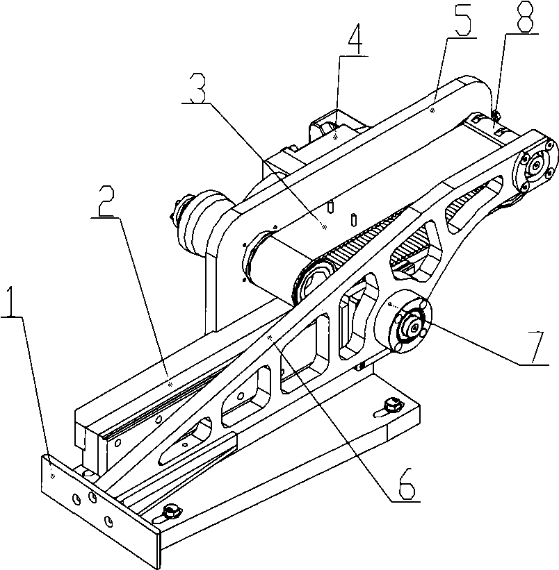
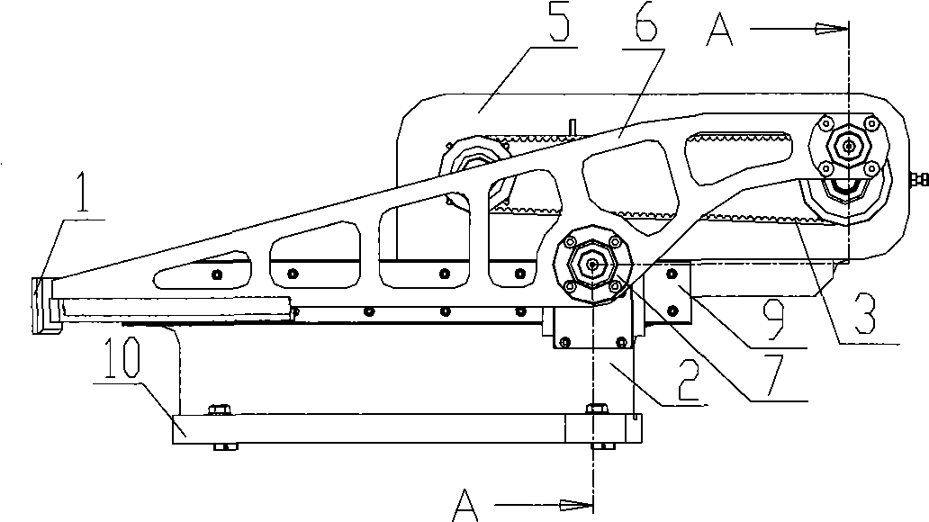
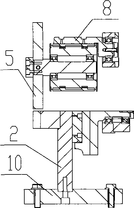
[0015] Embodiment 1: refer to Figure 1-7 . The stacker product pushes out the oblique push device, the push plate 1 is connected to the front end of the movement plate 6 and the connection surface of the push plate 1 is obliquely connected to the end face of the movement plate 6, and the middle part of the movement plate 6 cooperates with the slider 9 and the connecting shaft 7 through the dovetail guide rail 2 The dovetail groove guide rail 2 is a sliding fit and slides along the dovetail groove guide rail 2, one side of the dovetail groove guide rail 2 is connected with the lower part of the installation frame 10, and the timing belt 3 is set on the timing belt driving shaft and the timing belt driven shaft and is located on the wall plate 5 The synchronous belt 3 drive shaft is driven by the servo motor 4 to drive the synchronous belt 3 to rotate, and the synchronous belt 3 is connected to the coupling shaft on the moving plate 6 through the connecting plate 8 thereon and ...

Embodiment 2

[0016] Embodiment 2: On the basis of Embodiment 1, the stacker product pushes out the oblique push method of the oblique push device, the servo motor 4 drives the synchronous belt drive shaft, the synchronous belt drive shaft drives the synchronous belt 3 to rotate, and the synchronous belt 3 drives the motion plate 6 movement and the synchronous movement of the ejection plate 1 connected with the movement plate 6. When the ejection plate 1 pushes out the products in the stacker and reaches the designated position, the connecting plate 8 in the synchronous belt 3 turns over the synchronous belt drive shaft, and the synchronous belt 3 Force motion plate 6 to be fulcrum with connecting shaft 7, force push-out plate 1 upwards to sway, and now synchronous belt 3 continues to drive connecting plate 8 and push-out plate 1 on motion plate 6 and motion plate and walks up the return movement of rocking. When the synchronous belt 3 drives the connecting plate 8 to move to its initial pos...


PUM


Abstract

The invention relates to an oblique pushing device and an oblique pushing method for pushing a product in a stacker. A pushing plate is connected with the front end of a moving plate; the middle part of the moving plate is matched with a slide block and a connecting shaft through a dovetail groove guide rail, is in slide fit with the dovetail groove guide rail, and slides along the dovetail groove guide rail; one side of the dovetail groove guide rail is connected with the lower part of a mounting rack; a synchronous belt is sleeved on a driving shaft and a driven shaft of the synchronous belt, and the driving shaft of the synchronous belt is driven by a servomotor to drive the synchronous belt to rotate; and the synchronous belt is connected with the connecting shaft on the moving plate through a connecting plate on the synchronous belt and drives the connecting shaft to move. The device and the method have the advantages of achieving the aim of forward and backward motion of the moving plate driven by the synchronous belt and the pushing plate on the moving plate, achieving the reciprocating motion of the moving plate and the pushing plate on the moving plate in the dovetail groove guide rail and achieving the upward warping return stroke motion after the moving plate drives the pushing plate to finish the pushing motion so as to achieve circular pushing and rotary resetting of the pushing plate, and achieving the match of the oblique pushing device in the same PLC controller with the high-speed stacker.

Description

technical field [0001] The invention relates to a stacker product pushing device and method for pushing out products in a stacker, belonging to the field of stacker equipment manufacturing. Background technique [0002] The applicant owns CN101249899A, titled "Sanitary Napkin Production Line High-Speed ​​Stacker and Stacking Method", the grouping ejection mechanism I is composed of guide rails, ejection cylinder assembly and motor drive assembly, and the two guide rails are located on the frame in parallel. Pushing out the cylinder assembly is located on the two guide rails, the motor drive assembly is located between the two guide rails, the drive shaft in the motor drive assembly is connected with the cylinder assembly and drives the cylinder assembly to move back and forth along the guide rails; the grouping ejection mechanism II consists of The cylinder assembly is formed and located on the frame; the two clamping output devices are composed of a chain support mechanism,...

Claims


Application Information

Patent Timeline
Patent Type & Authority Applications(China)
IPC IPC(8): B65G57/00
Inventor 赵银祥徐源泉张培栋许蔚
Owner ZHEJIANG YONGCHUANG MACHINERY
Why Eureka
Try Eureka