
An engineering auxiliary platform for lathe monitoring

An auxiliary platform and engineering technology, applied in the field of lathe monitoring, which can solve the problems of troublesome use, inability to move left and right, and heavy adjustment workload.

Active Publication Date: 2018-12-07
GUIZHOU UNIV
View PDF5 Cites 0 Cited by
  • Summary
  • Abstract
  • Description
  • Claims
  • Application Information

AI Technical Summary

Problems solved by technology

[0004] The object of the present invention is to provide an engineering auxiliary platform for lathe monitoring, to solve the problem that the existing camera proposed in the above background technology can only rotate at an angle, cannot move left and right on the platform, the monitoring effect is not comprehensive, and the existing Generally, the concentricity detector is placed separately on the detection platform, and the workload of independent adjustment is large and troublesome to use.

Method used


Image

  • An engineering auxiliary platform for lathe monitoring
  • An engineering auxiliary platform for lathe monitoring

Examples


Embodiment Construction

[0014] The following will clearly and completely describe the technical solutions in the embodiments of the present invention with reference to the accompanying drawings in the embodiments of the present invention. Obviously, the described embodiments are only some, not all, embodiments of the present invention. Based on the embodiments of the present invention, all other embodiments obtained by persons of ordinary skill in the art without creative efforts fall within the protection scope of the present invention.

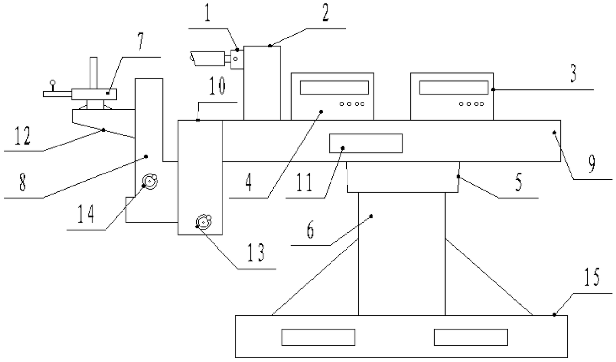
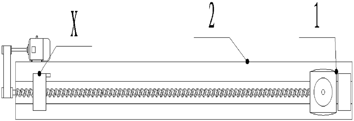
[0015] see Figure 1-2 , the present invention provides a technical solution: an engineering auxiliary platform for lathe monitoring, including a camera 1, a carriage 2, a noise monitor 3, a vibration monitor 4, a rotary table 5, a column 6, a concentricity detector 7, a A sliding frame 8, a platform 9, a second sliding frame 10, a spirit level 11, a detector placement platform 12, a first handwheel 13, a second handwheel 14 and a base 15, the camera 1 is located o...


PUM


Abstract

The invention discloses an auxiliary engineering platform for lathe monitoring. The auxiliary engineering platform comprises a detector putting platform, a first hand wheel, a second hand wheel and a base, wherein a camera is positioned on the left end surface of a slide frame; a noise monitoring instrument and a vibration monitoring instrument are mounted at the top end of the platform; a rotary table is connected with a stand column; the first hand wheel and the second hand wheel are separately positioned on the front side end surface of a first slide frame and the front side end surface of a second slide frame; and a concentricity detector is arranged on the top end surface of the detector putting platform. According to the auxiliary engineering platform for lathe monitoring disclosed by the invention, the vibration monitoring instrument, the concentricity detector and the noise monitoring instrument are directly mounted at the upper end of the detector putting platform, and the noise monitoring instrument and the vibration monitoring instrument are used for performing related detection on lathe equipment; the movable camera is arranged and moves back and forth through matching of a motor and a limiting switch, so that monitoring records for a position of a positioning performing element and change monitoring for sensing a surrounding environment are completed.

Description

technical field [0001] The invention relates to the technical field of lathe monitoring, in particular to an engineering auxiliary platform for lathe monitoring. Background technique [0002] In mechanical processing, in order to accurately locate the position of the actuator and perceive changes in the surrounding environment, it is necessary to monitor each operation link. Generally, a camera needs to be installed for monitoring. [0003] The existing camera can only rotate at an angle, and cannot move left and right on the platform, so the monitoring effect is not comprehensive. Moreover, the existing detection platform generally places a concentricity detector separately, and the separate adjustment workload during use is heavy and troublesome to use. Contents of the invention [0004] The purpose of the present invention is to provide an engineering auxiliary platform for lathe monitoring, to solve the problem that the existing camera proposed in the above background ...

Claims


Application Information

Patent Timeline
Patent Type & Authority Patents(China)
IPC IPC(8): B23Q17/00
CPCB23Q17/00
Inventor 李政杰李少波黄海松唐世灏杜飞龙谢永康
Owner GUIZHOU UNIV
Learn More