Supercharge Your Innovation With Domain-Expert AI Agents!

Fixing element for a bone fragment

A technology for fastening components and components, which is applied in the direction of fixators, internal fixators, connecting components, etc., and can solve problems such as femoral neck fractures that are not applicable

Inactive Publication Date: 2011-05-11
RESOIMPLANT
View PDF5 Cites 0 Cited by
  • Summary
  • Abstract
  • Description
  • Claims
  • Application Information

AI Technical Summary

Problems solved by technology

[0005] However, the known fastening elements are not suitable for the treatment of fractures of the femoral neck of the femur

Method used


Image

  • Fixing element for a bone fragment
  • Fixing element for a bone fragment
  • Fixing element for a bone fragment

Examples


Embodiment Construction

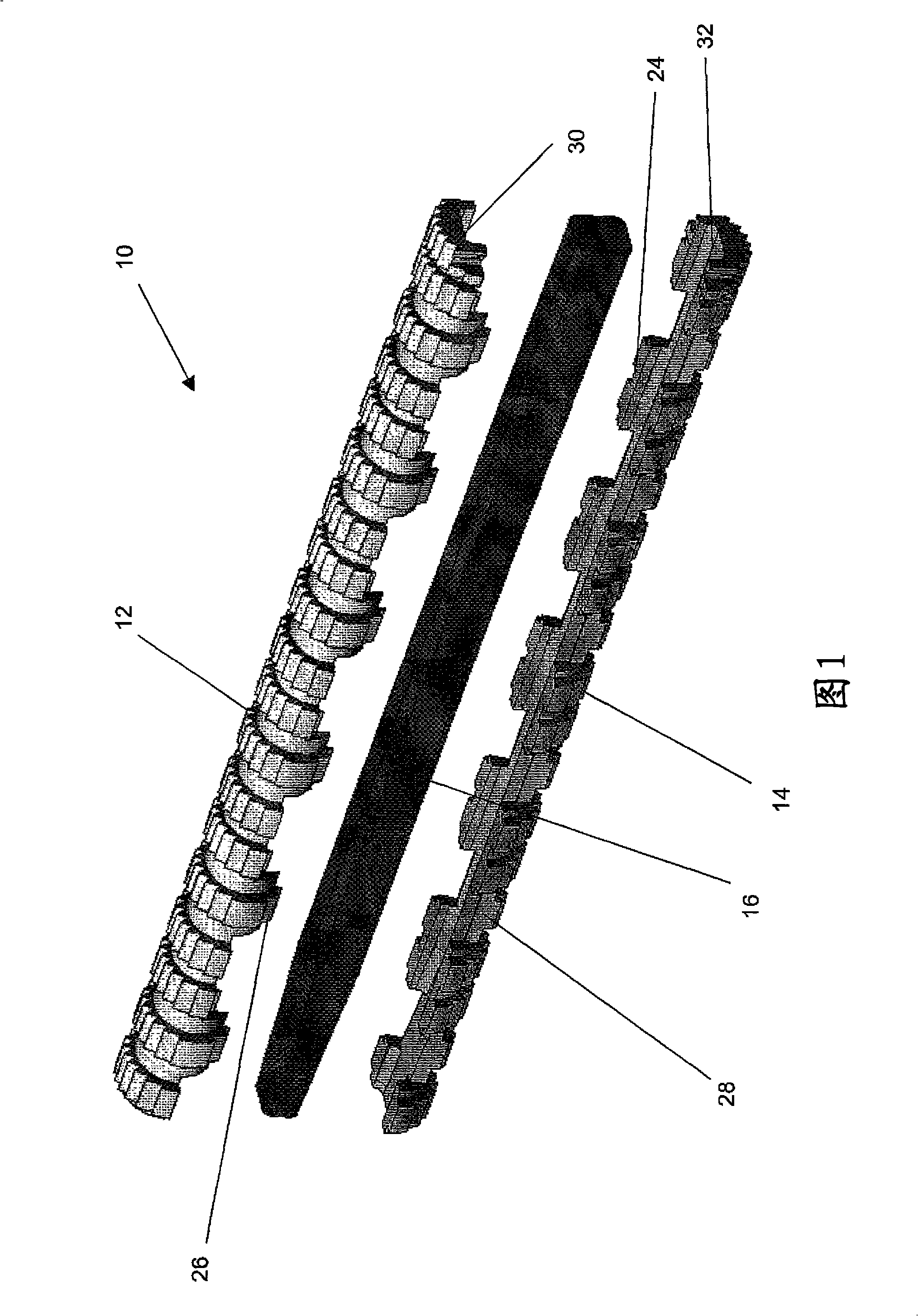
[0021] FIG. 1 shows a preferred embodiment of a fastening element 10 . The fastening element 10 has two outer partial elements 12 and 14 which surround an expansion element 16 .

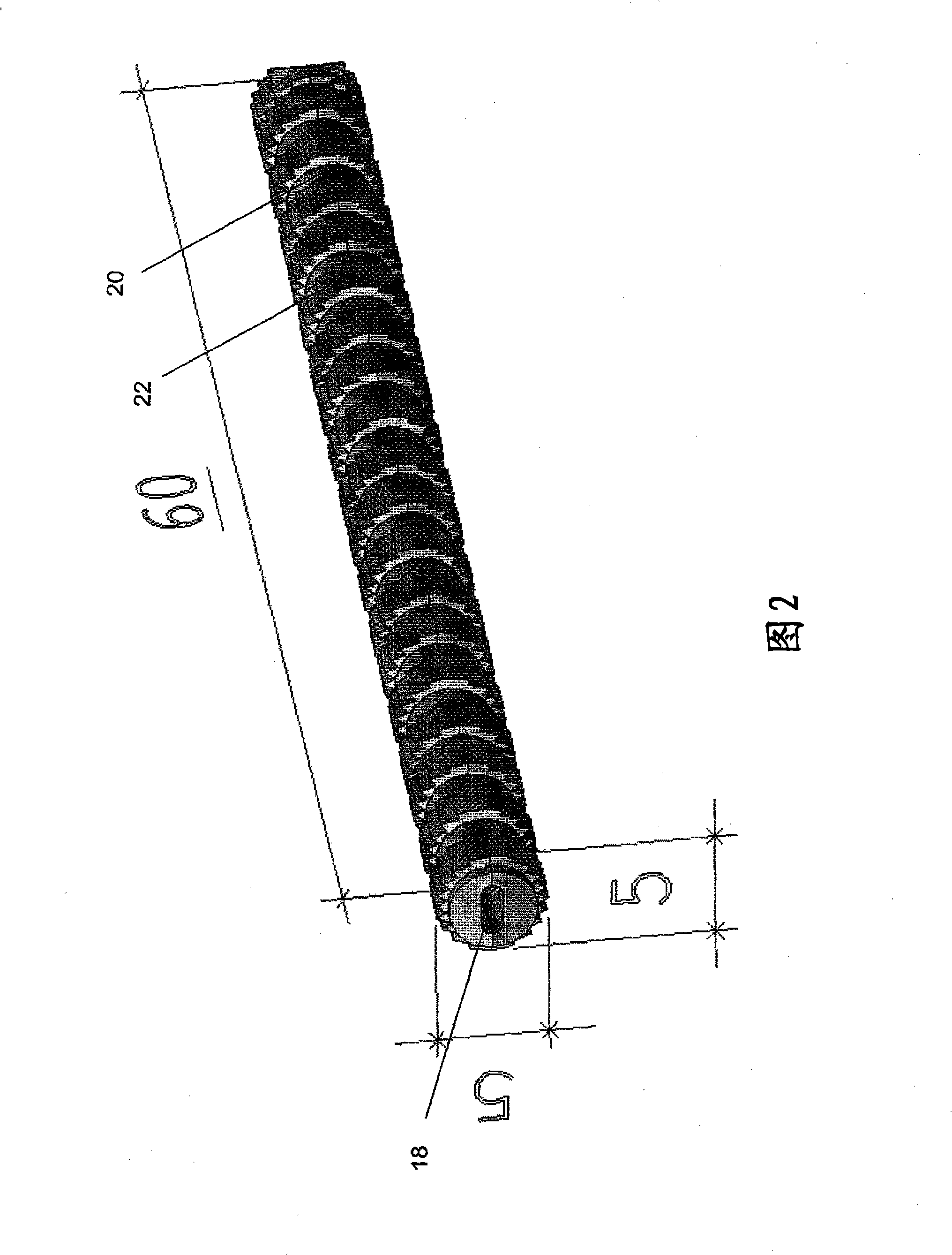
[0022] FIG. 2 shows the fastening element 10 in the closed state in which the two outer partial elements 12 and 14 are pressed directly against each other. It can be seen that the two partial elements surround a cavity 18 into which the expansion element 16 can be introduced.

[0023] FIG. 3 shows the fastening element 10 in the expanded state in which the expansion element 16 is inserted into the cavity 18 .

[0024] The two outer partial elements 12 and 14 are formed in such a way that in the tight state of the fastening element shown in FIG. 2 they give this fastening element a cylindrical basic shape in which alternately arranged There is a longitudinal section 20 with a circular cross-section and a longitudinal section 22 with a star-shaped cross-section. In the exemplary embodiment, the enti...


PUM


Abstract

The invention relates to a fixing element, in particular an anchor, for fixing bone fragments or similar, which has at least two parallel outer sub-elements and an expansion element that are designed and arranged in relation to one another in such a way that the fixing element can be converted from a compact state into an expanded state by means of the expansion element. The two sub-elements encompass a cavity for the expansion element, said cavity having anti-friction surfaces for the expansion element that run parallel to the longitudinal axis of the fixing element. In the compact state of the fixing element, said surfaces are situated at a distance from one another, which is smaller than the distance between anti-friction surfaces of the expansion element that likewise run parallel to the longitudinal axis of the fixing element. According to the invention, the anti-friction surfaces delimiting the cavity of the sub-elements and the anti-friction surfaces of the expansion element aredesigned and arranged in relation to one another in such a way that the introduction of the expansion element into the cavity between the sub-elements forces apart said elements in a lateral direction, converting the fixing element into its laterally expanded state.

Description

technical field [0001] The invention relates to a fastening element, in particular an anchor, for fixing eg bone fragments, and also to a fastening element for surgical applications. [0002] The fastening element is divided into at least two partial elements in the longitudinal direction and has an expansion element. These elements are formed and arranged relative to each other in such a way that the fastening element is transferred from a compacted state into an expanded state by means of the expansion element. For this purpose, the two partial elements enclose a cavity for the expansion element, which cavity has a sliding surface for the expansion element running parallel to the longitudinal axis of the fastening element. In the compact state of the fastening element, the sliding surfaces have a distance from one another which is smaller than the distance between the sliding surfaces of the expansion element, which likewise extend parallel to the longitudinal axis of the f...

Claims


Application Information

Patent Timeline
Patent Type & Authority Patents(China)
IPC IPC(8): A61B17/74A61B17/68F16B13/12
CPCA61B17/68A61B17/683A61B17/72A61B17/7258A61B17/7283A61B17/74A61B2017/00004A61P5/30F16B13/0825F16B13/126
Inventor 京特·洛布
Owner RESOIMPLANT
Features
  • R&D
  • Intellectual Property
  • Life Sciences
  • Materials
  • Tech Scout
  • Unparalleled Data Quality
  • Higher Quality Content
  • 60% Fewer Hallucinations
Learn More