Backlight module and diffusion plate thereof

A technology of backlight module and diffuser, applied in optics, optical components, nonlinear optics, etc., can solve the problems of reducing light utilization, increasing the number of light interfaces, and light loss.

Active Publication Date: 2010-01-13
深圳市诚誉兴光电有限公司
View PDF0 Cites 7 Cited by
  • Summary
  • Abstract
  • Description
  • Claims
  • Application Information

AI Technical Summary

Problems solved by technology

[0005] However, when the light is transmitted in the prism sheet 10 and the upper diffusion sheet 14, part of the light will be abso

Method used


Image

  • Backlight module and diffusion plate thereof
  • Backlight module and diffusion plate thereof
  • Backlight module and diffusion plate thereof

Examples


Embodiment Construction

[0018] The backlight module and its diffuser plate of the present invention will be further described in detail below with reference to the drawings and embodiments.

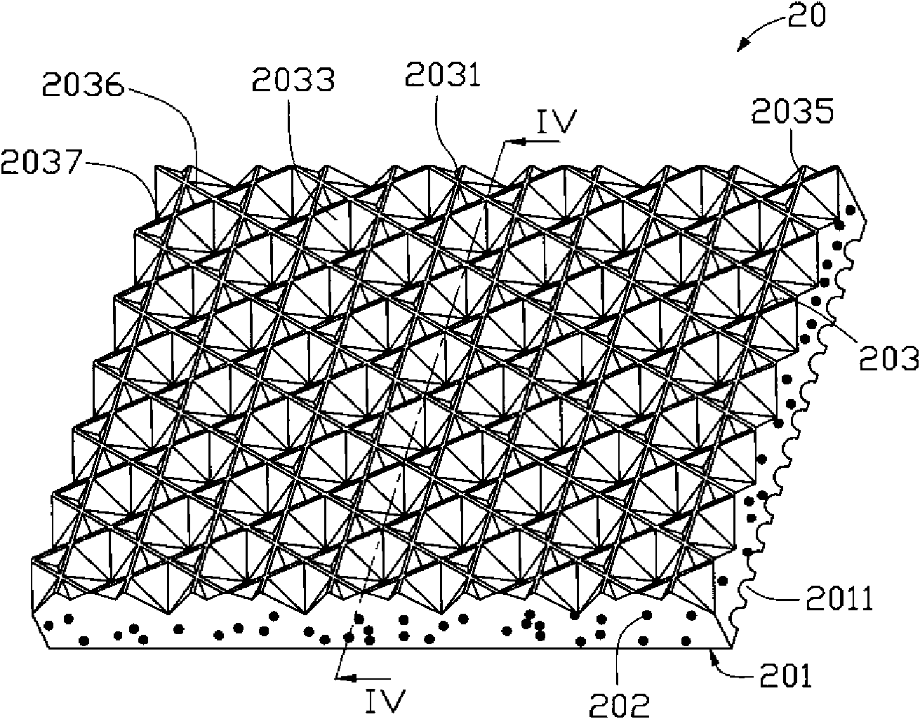
[0019] See image 3 and Figure 4 , shows a diffuser plate 20 according to a preferred embodiment of the present invention, which includes a body having a first surface 201 and a second surface 203 opposite to the first surface 201 .

[0020] The main body is made of transparent material, which is one or a mixture of polymethyl methacrylate, polycarbonate, polystyrene, styrene-methyl methacrylate copolymer. The body also includes scattering particles 202 dispersed in the transparent material. The scattering particles 202 are one or a combination of titanium dioxide particles, silicon dioxide particles, and acrylic resin particles, which can scatter and diffuse light irradiated thereon. It can be understood that by adjusting the composition of the transparent material and the diffusing particles 200, the light...


PUM

PropertyMeasurementUnit
Angleaaaaaaaaaa

Abstract

A backlight module comprises a frame, a light source and a diffusion plate; wherein, the light source is positioned in the frame; the diffusion plate is positioned above the light source and comprises a body; the body is made of transparent materials in which scattering particles are dispersed and comprises a first surface and a second surface opposite to the first surface; the first surface is provided with a plurality of mutually parallel long strip arc grooves; the second surface is provided with a plurality of triangular pyramid shaped grooves and hexagonal pyramid shaped grooves; each triangular pyramid shaped groove is enclosed by three adjacent hexagonal pyramid shaped grooves. The invention also provides the diffusion plate adopted by the backlight module. The backlight module has the advantages of improving effective utilization ratio of light and enjoying uniformity of light emission.

Description

technical field [0001] The invention relates to a backlight module and a diffusion plate thereof, in particular to a backlight module for liquid crystal display and a diffusion plate thereof. Background technique [0002] See figure 1 , shows a conventional direct-lit backlight module 100 , which includes a frame 11 , a plurality of light sources 12 disposed inside the frame 11 , and a diffusion plate 13 disposed above the light sources 12 . [0003] In use, the light generated by the plurality of light sources 12 can be diffused after entering the diffuser plate 13 . However, after being diffused by the diffuser plate 13, the angles at which light emerges from the diffuser plate 13 become more chaotic, so that its brightness in a specific viewing angle range is not high; It is still often difficult for the plate 13 to directly diffuse the light from the light source 12 evenly, so that the light emitted from the diffuser plate 13 is prone to light source afterimages, that ...

Claims


Application Information

Patent Timeline
IPC IPC(8): G02F1/13357G02B5/02G02B1/04
Inventor 章绍汉
Owner 深圳市诚誉兴光电有限公司
Why Eureka
Try Eureka