Linked linear voltage regulation non-excitation tap switch

A technology of tap changer and linear voltage regulation, which is applied to transformers, variable transformers, prior contact arrangements, etc., can solve problems such as unfavorable layout and material-saving design, transformer coil short circuit, transformer cost increase, etc., to achieve easy operation and maintenance, Simplified structure and high operational reliability

Inactive Publication Date: 2011-10-19
WUHAN TAIPU TRANSFORMER CHANGER
View PDF5 Cites 0 Cited by
  • Summary
  • Abstract
  • Description
  • Claims
  • Application Information

AI Technical Summary

Problems solved by technology

The coil taps of each phase correspond to one phase contact layer of the switch, that is, the single, two, and three-phase are respectively one, two, and three-layer contacts. The wiring principle between the contacts of each layer of the three-phase is completely consistent with the voltage regulation sequence. , the output contact is connected to the phase or out-of-phase coil according to the needs, but this structure has a great potential for accidents, that is, when the moving contact stays in the 1-2 or 3-4 tap due to misoperation, the transformer coil There will be a short circuit accident
In addition, when the switch has many voltage regulation positions, more static contacts need to be configured. The large distribution of static contacts will also increase the diameter of the switch, which is not conducive to the layout of the switch in the transformer and material-saving design, and the cost of the transformer will also increase. high

Method used


Image

  • Linked linear voltage regulation non-excitation tap switch
  • Linked linear voltage regulation non-excitation tap switch
  • Linked linear voltage regulation non-excitation tap switch

Examples


Embodiment Construction

[0024] Embodiments of the present invention will be further described below in conjunction with the accompanying drawings.

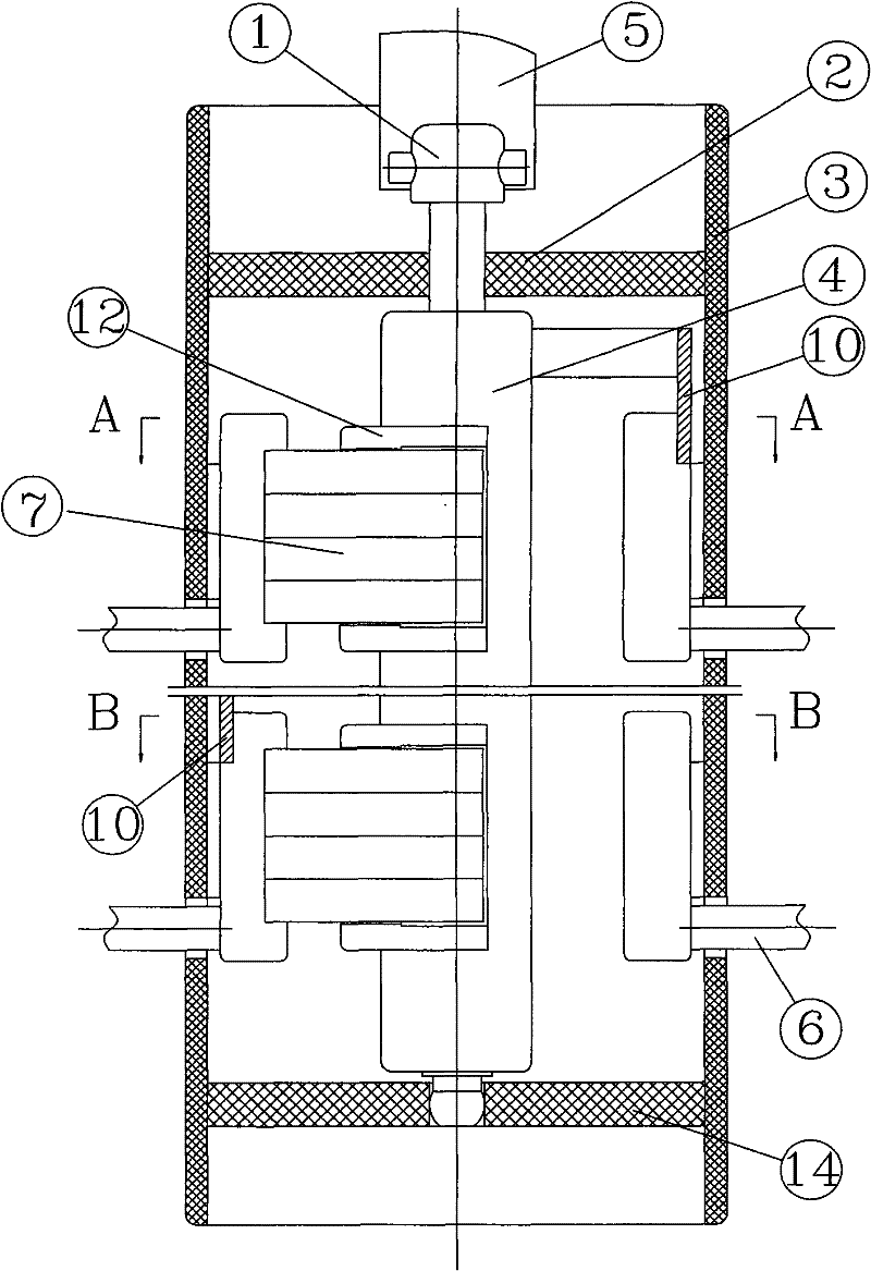
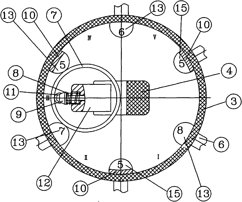
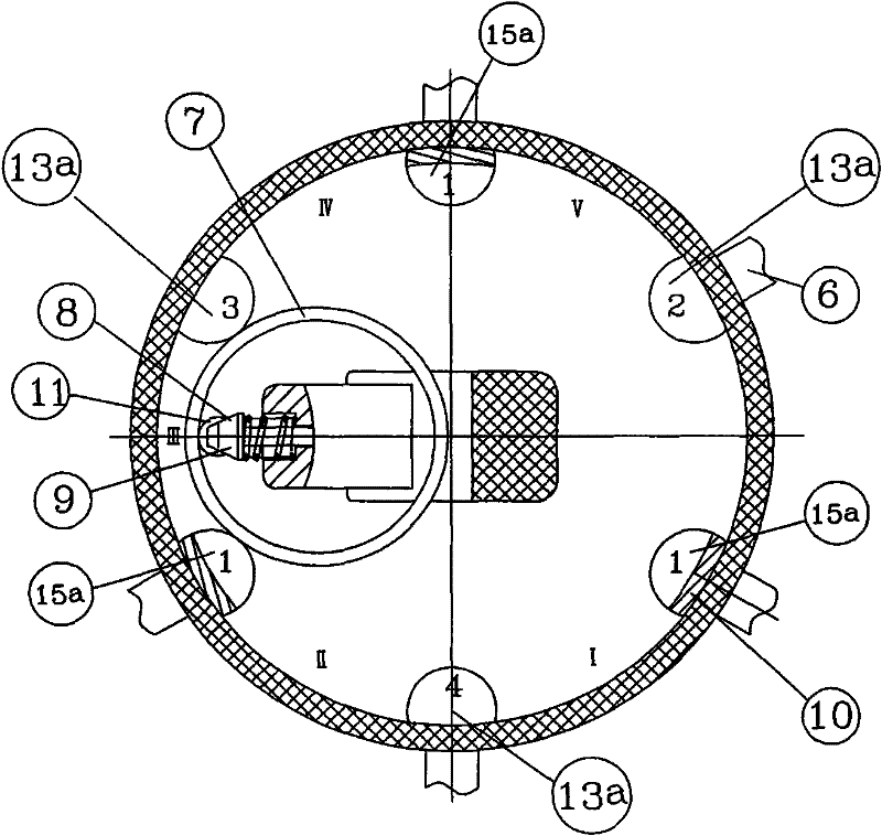
[0025] The first embodiment of the present invention is Figure 1~4 As shown, it is a single-phase drum-shaped linkage linear voltage-regulating off-excitation tap-changer, including a cylindrical insulator 3 and upper and lower supports 2, 14, and a rotating shaft is installed in the middle of the upper and lower supports. 4 and the transmission shaft 1 at its upper end, the insulating shaft is connected to the operating mechanism 5 through the transmission shaft at the upper end, and two layers of static contacts correspondingly distributed along the circumferential direction are arranged on the inner side of the insulating cylinder, and the two layers of static contacts are separated from each other up and down. Insulation, the static contact is a cylindrical static contact, and the rear end of the static contact is a lead joint 6, which is used to co...


PUM


Abstract

The invention relates to a linked linear voltage regulation non-excitation tap switch for a transformer, which is characterized in that: each phase corresponding to the switch is provided with two layers of static contacts; one layer of the two layers of static contacts of each phase is provided with static contacts of an upper voltage regulation tap of a linked voltage regulation coil and staticcontacts of a midpoint tap, and the two kinds of static contacts of the taps are distributed mutually at intervals; the other layer is provided with static contacts of a lower voltage regulation tap of the linked voltage regulation coil and static contacts of an output tap, and the two kinds of static contacts of the taps are distributed mutually at intervals; two adjacent static contacts form a tap position, and the tap positions are distributed along the circumferential direction in reduced progressively sequence from large to small; and only one maximum tap position in one layer of the twolayers of static contacts set in each phase corresponds to a maximum tap position in the other layer. The tap switch is simple and compact in structure and reasonable in setting, achieves multi-tap linear voltage regulation by using less voltage regulation coil taps, is convenient to operate, has no short connected tap position and high working reliability, and is small in volume to greatly simplify the transformer structure and reduce manufacturing cost and use cost.

Description

technical field [0001] The invention relates to a linkage linear voltage regulation non-excitation tap changer for a transformer. Background technique [0002] In the Chinese patent CN2468142Y, a non-excitation linear pressure regulating drum tap changer is disclosed. It is to set the output contact between two adjacent tap taps of each phase, and use the moving contact to bridge the position of each gear. Tap taps and output taps are used to realize linear voltage regulation, and the structure is relatively simple. The coil taps of each phase correspond to one phase contact layer of the switch, that is, the single, two, and three-phase are respectively one, two, and three-layer contacts. The wiring principle between the contacts of each layer of the three-phase is completely consistent with the voltage regulation sequence. , the output contact is connected to the phase or out-of-phase coil according to the needs, but this structure has a great potential for accidents, that...

Claims


Application Information

Patent Timeline
Patent Type & Authority Patents(China)
IPC IPC(8): H01F29/04H01H1/56
Inventor 刘刚
Owner WUHAN TAIPU TRANSFORMER CHANGER
Why Eureka
Try Eureka