Resource allocation method and resource allocation system
What is AI technical title?
AI technical title is built by PatSnap AI team. It summarizes the technical point description of the patent document.
A technology of resource allocation and correspondence table, applied in transmission systems, allocation standards, digital transmission systems, etc., can solve problems such as system performance degradation and improper cooperation, and achieve the effect of high theoretical spectral efficiency
Inactive Publication Date: 2012-12-05
ZTE CORP
View PDF0 Cites 0 Cited by
Summary
Abstract
Description
Claims
Application Information
AI Technical Summary
This helps you quickly interpret patents by identifying the three key elements:
Problems solved by technology
Method used
Benefits of technology
Problems solved by technology
[0008] The technical problem to be solved by the present invention is to provide a resource allocation method and system, which solves the problem of system performance degradation caused by improper cooperation of system uplink RB allocation, power control and adaptive modulation and coding (Automatic Modulation Code, AMC)
Method used
Image
Click on the blue label to locate the original text in one second.
Reading with bidirectional positioning of images and text.
Examples
example 1
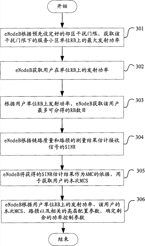
[0064] Example 1 provides a cooperative method of uplink RB allocation, AMC and power control, such as image 3 shown, including the following steps:
[0065] In step 301, the eNodeB acquires the maximum transmit power on the unit RB of the serving cell under the interference threshold according to the preset neighbor cell interference threshold, denoted as; P MAXfromInterference
[0066] Assumption: the user’s signal transmission power is P, the path loss to the serving cell is PL, the path loss to the neighbor cell eNodeBi is PLi′, and the neighbor cell eNodeBi interference threshold is set to Pi InterferenceTh , the number of adjacent eNodeBs i≤N Neighbor , then P-PLi′≤Pi InterferenceTh When i=1,...,N Neighbor , where N Neighbor Indicates the number of neighboring cells of the current serving cell;
[0067] so as to get P MAXfromInterfercnce =Min{Pi InterferenceTh +PLi'}, where i=1,...,N Neighbor
[0068] Step 302, the eNodeB obtains the transmit power of the user...
example 2
[0083] Example 2 provides a cooperative method of uplink RB allocation, AMC and power control, such as Figure 4 As shown, the method includes the following steps:
[0084] In step 401, the eNodeB obtains the maximum transmit power on the unit RB of the serving cell under the interference threshold according to the preset neighbor cell interference threshold, denoted as P MAXfromInterference ;
[0085] Such as Figure 5 As shown, the wireless network model with the number of neighboring cells as one is taken as an example; the signal transmission power of the serving cell is set to P, the path loss is PL, the path loss when reaching the neighboring cell eNodeB is PL′, and the neighboring cell interference threshold is set to P InterferenceTh , then P-PL′≤P InterferenceTh ;
[0086] so as to get P MAXfromInterfercnce =P InterferenceTh +PL'
[0087] Step 402, the eNodeB obtains the transmit power of the user on the unit RB;
[0088] The maximum transmit power of the desi...
PUM
Abstract
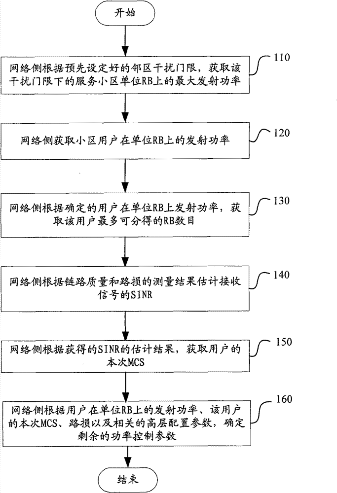
A method and a system for resource allocation are disclosed in the present invention. The method comprises: a network side, according to a preset interference threshold of neighboring cells, determining a transmission power of a cell user on a unit Resource Block (RB), and then determining to obtain the maximum number of RBs which can be allocated to the cell user according to the transmission power of the cell user on the unit RB; the network side, according to the link quality, the path loss condition and the transmission power of the cell user on the unit RB, obtaining a predicted value of the Signal Interface Noise Ratio (SINR) of the received signal, and then obtaining the current Modulation Code Scheme (MCS) of the cell user according to the predicted value of the SINR; and the network side determining a power control parameter according to the transmission power of the cell user on the unit RB and the current MCS of the cell user. In the present invention, the RB allocation, the power control parameter and the Automatic Modulation Code (AMC) work together to reach the maximum throughput of the system, thus guaranteeing the maximum theoretic spectral efficiency.
Description
technical field [0001] The present invention relates to the field of wireless communication, in particular, to a resource allocation method and system. Background technique [0002] In a Long-Term Evolution system (LTE, Long-Term Evolution), during data transmission, uplink / downlink time-frequency domain physical resources are formed into resource blocks (Resource Block, RB), which are scheduled and allocated as physical resource units. In the case of Normal CP (cyclic prefix), an RB contains 12 consecutive subcarriers in the frequency domain and 7 consecutive Orthogonal Frequency Division Multiplexing (OFDM) symbols in the time domain, that is, the frequency domain width is 180kHz , the time length is 0.5ms. [0003] In LTE uplink resource allocation, the uplink scheduler of the base station (eNodeB) needs to allocate a certain number of RBs, transmit power and select an appropriate modulation and coding scheme (Modulation CodeScheme, MCS) for users. There is the followin...
Claims
Application Information
Patent Timeline
Application Date:The date an application was filed.
Publication Date:The date a patent or application was officially published.
First Publication Date:The earliest publication date of a patent with the same application number.
Issue Date:Publication date of the patent grant document.
PCT Entry Date:The Entry date of PCT National Phase.
Estimated Expiry Date:The statutory expiry date of a patent right according to the Patent Law, and it is the longest term of protection that the patent right can achieve without the termination of the patent right due to other reasons(Term extension factor has been taken into account ).
Invalid Date:Actual expiry date is based on effective date or publication date of legal transaction data of invalid patent.

