Resource allocation method and resource allocation system

A resource allocation and corresponding relationship table technology, applied in transmission systems, allocation standards, digital transmission systems, etc., can solve problems such as system performance degradation and improper collaboration, and achieve high theoretical spectrum efficiency

Inactive Publication Date: 2010-05-19
ZTE CORP
View PDF0 Cites 50 Cited by
  • Summary
  • Abstract
  • Description
  • Claims
  • Application Information

AI Technical Summary

Problems solved by technology

[0008] The technical problem to be solved by the present invention is to provide a resource allocation method and system, which solves the problem of system performance degradation caused by improper cooperation of system uplink RB allocation, power control and adaptive modulation and coding (Automatic Modulation Code, AMC)

Method used


Image

  • Resource allocation method and resource allocation system
  • Resource allocation method and resource allocation system
  • Resource allocation method and resource allocation system

Examples


example 1

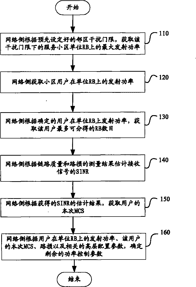
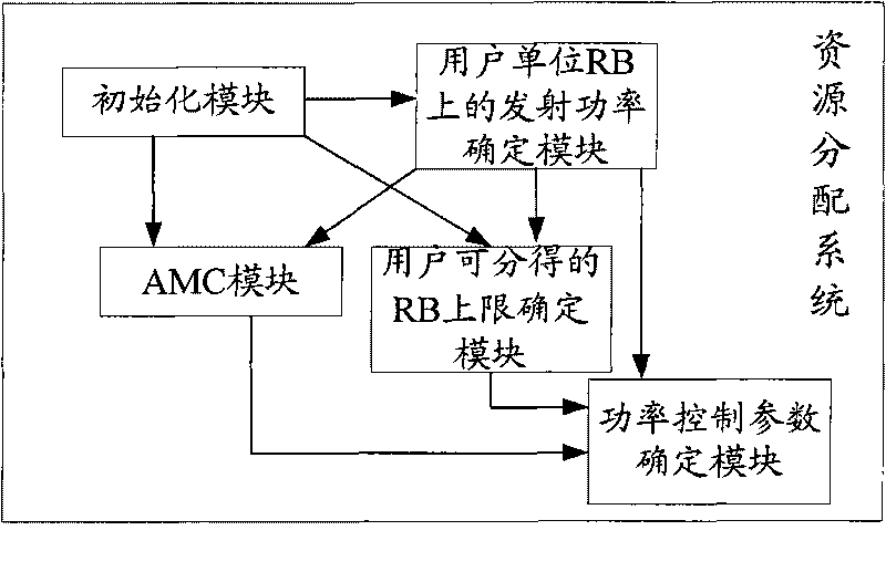
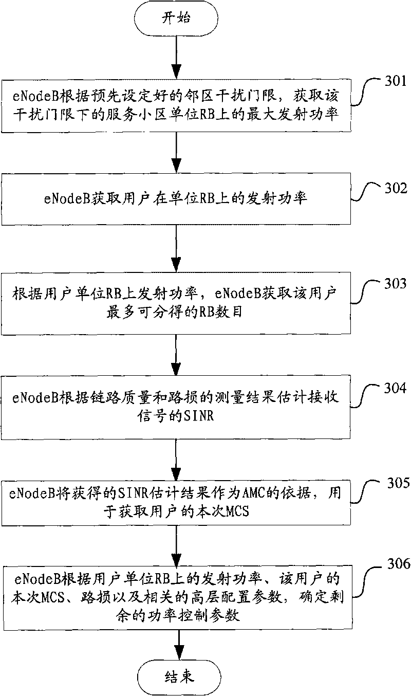
[0064] Example 1 provides a cooperative method of uplink RB allocation, AMC and power control, such as image 3 shown, including the following steps:

[0065] In step 301, the eNodeB acquires the maximum transmit power on the unit RB of the serving cell under the interference threshold according to the preset neighbor cell interference threshold, denoted as; P MAXfromInterference

[0066] Assumption: the user’s signal transmission power is P, the path loss to the serving cell is PL, the path loss to the neighbor cell eNodeBi is PLi′, and the neighbor cell eNodeBi interference threshold is set to Pi InterferenceTh , the number of adjacent eNodeBs i≤N Neighbor , then P-PLi′≤Pi InterferenceTh When i=1,...,N Neighbor , where N Neighbor Indicates the number of neighboring cells of the current serving cell;

[0067] so as to get P MAXfromInterfercnce =Min{Pi InterferenceTh +PLi'}, where i=1,...,N Neighbor

[0068] Step 302, the eNodeB obtains the transmit power of the user...

example 2

[0083] Example 2 provides a cooperative method of uplink RB allocation, AMC and power control, such as Figure 4 As shown, the method includes the following steps:

[0084] In step 401, the eNodeB obtains the maximum transmit power on the unit RB of the serving cell under the interference threshold according to the preset neighbor cell interference threshold, denoted as P MAXfromInterference ;

[0085] Such as Figure 5 As shown, the wireless network model with the number of adjacent cells as one is taken as an example; the signal transmission power of the serving cell is set to P, the path loss is PL, the path loss when reaching the neighboring cell eNodeB is PL′, and the adjacent cell interference threshold is set to P InterferenceTh , then P-PL′≤P InterferenceTh ;

[0086] so as to get P MAXfromInterfercnce =P InterferenceTh +PL'

[0087] Step 402, the eNodeB obtains the transmit power of the user on the unit RB;

[0088] The maximum transmit power of the design use...


PUM


Abstract

The invention discloses a resource allocation method and a resource allocation system. The resource allocation method comprises that: a network side determines transmission power on a cell user unit RB according to a preset neighborhood interference threshold; the network side acquires a predicted value of the SINR of received signals according to link quality, road damage condition and the transmission power on the user unit RB, and acquires an MCS of the user according to the predicted value of the SINR; and the network side determines a power control parameter according to the acquired transmission power on the user unit RB and the MCS of the user. The resource allocation method solves the problem of the performance reduction of the system caused by improper cooperation among uplink RBallocation, power control and AMC of the system.

Description

technical field [0001] The present invention relates to the field of wireless communication, in particular, to a resource allocation method and system. Background technique [0002] In a Long-Term Evolution system (LTE, Long-Term Evolution), during data transmission, uplink / downlink time-frequency domain physical resources are formed into resource blocks (Resource Block, RB), which are scheduled and allocated as physical resource units. In the case of Normal CP (cyclic prefix), an RB contains 12 consecutive subcarriers in the frequency domain and 7 consecutive Orthogonal Frequency Division Multiplexing (OFDM) symbols in the time domain, that is, the frequency domain width is 180kHz , the time length is 0.5ms. [0003] In LTE uplink resource allocation, the uplink scheduler of the base station (eNodeB) needs to allocate a certain number of RBs, transmit power and select an appropriate modulation and coding scheme (Modulation CodeScheme, MCS) for users. There is the followin...

Claims


Application Information

Patent Timeline
Patent Type & Authority Applications(China)
IPC IPC(8): H04W72/08
CPCH04W52/367H04B17/0075H04L1/0021H04W52/262H04W52/242H04L5/006H04L5/0046H04W52/143H04L5/0066H04W72/04H04W28/048H04W72/085H04B17/373H04W28/04H04W72/542
Inventor 张庆宏王衍文
Owner ZTE CORP
Why Eureka
Try Eureka