Supergravity dewatering device for natural gas

A technology for dehydration equipment and natural gas, which is applied in the fields of gas fuel, petroleum industry, dispersed particle separation, etc., can solve the problems of incomplete dehydration and separation of natural gas, inconvenient combustion and utilization, and large equipment area, and achieves high water removal efficiency, Easy to promote and use, small footprint

Inactive Publication Date: 2010-06-30
西安恒旭科技股份有限公司
View PDF4 Cites 4 Cited by
  • Summary
  • Abstract
  • Description
  • Claims
  • Application Information

AI Technical Summary

Problems solved by technology

[0002] At present, most of the natural gas produced in the oil field is sent to the oil and gas treatment plant for processing through the gathering pipeline. The unpurified natural gas is usually called wet gas, which contains a large amount of water (H 2 O) and carbon dioxide (CO 2 ), transporting unpurified wet gas will cause serious corrosion to the gathering and transportation pipelines. At the same time, if the wet gas is not treated, it will be inconvenient to burn and use nearby. In the field of oil and gas gathering and transportation natural gas separation technology in the petroleum industry , the separation of natural gas generally adopts the method of gravity separation. Due to the small diameter of the liquid droplets, the dehydration and separation of natural gas is not complete. In addition, the conventional gravity separation has a large area of ​​equipment, large construction investment, and many operating points, which is not easy to manage and efficient. Low and other issues

Method used


Image

  • Supergravity dewatering device for natural gas
  • Supergravity dewatering device for natural gas

Examples


Embodiment Construction

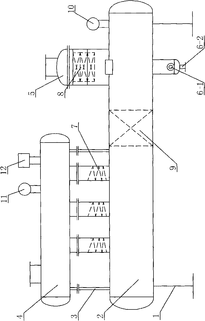
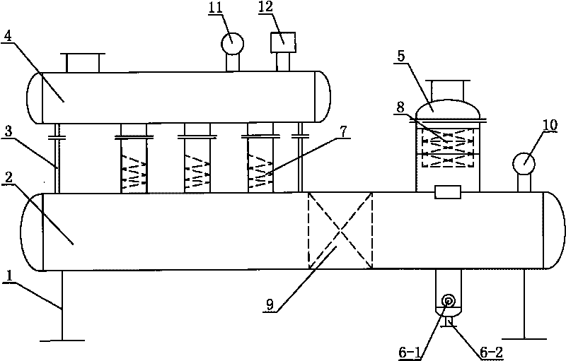
[0022] Such as figure 1 The shown natural gas supergravity dehydration equipment includes a bottom frame 1, a tank 2 for flashing water-containing natural gas is installed on the upper side of the bottom frame 1, and the upper side of the tank 2 is installed through the upper frame 3. In the tank two 4 for buffering the water-containing natural gas, the upper side and the lower side of the other end of the tank one 2 are respectively provided with a mist catcher 5 for removing the moisture contained in the natural gas again and a liquid discharge pipe for discharging the liquid inside the tank one 2. Tank one 2 and tank two 4 are connected through a plurality of supergravity separation pipes 7, and the inside of the mist catcher 5 is provided with a wire mesh 8, and the interior of the tank one 2 is located between the mist catcher 5 and the supergravity separation pipe 7 The position between is provided with packing device 9.

[0023] Such as figure 1 As shown, the tank one...


PUM


Abstract

The invention discloses a supergravity dewatering device for natural gas, comprising a bottom frame, wherein a first tank used for flash evaporation of natural gas containing water is arranged on the upside of the bottom frame; a second tank used for buffering the natural gas containing water is arranged on the upside of one end of the first tank through an upper frame; a spray catcher used for getting rid of water contained in the natural gas for the second time is arranged at the upper side of the other end of the first tank, and a liquid discharging pipe used for discharging liquid inside the first tank is arranged at the lower side thereof; the first tank and the second tank are interconnected through a plurality of gravity separator tubes; and a silk screen is arranged inside the spray catcher, and a filling device is arranged between the spray catcher and the separator tubes inside the first tank. The supergravity dewatering device for natural gas has the advantages of safe and reliable running, low running cost, capability of separating liquid drops having radius of 10 micrometers, less operation points, easy management and usage, large processing quantity, low occupation area, low production cost and easy popularization.

Description

technical field [0001] The invention belongs to the technical field of petroleum gas treatment and processing, and in particular relates to a natural gas supergravity dehydration equipment for separating natural gas and performing preliminary dehydration on natural gas. Background technique [0002] At present, most of the natural gas produced in the oil field is sent to the oil and gas treatment plant for processing through the gathering pipeline. The unpurified natural gas is usually called wet gas, which contains a large amount of water (H 2 O) and carbon dioxide (CO 2 ), transporting unpurified wet gas will cause serious corrosion to the gathering and transportation pipelines. At the same time, if the wet gas is not treated, it will be inconvenient to burn and use nearby. In the field of oil and gas gathering and transportation natural gas separation technology in the petroleum industry , the separation of natural gas generally adopts the method of gravity separation. D...

Claims


Application Information

Patent Timeline
Patent Type & Authority Applications(China)
IPC IPC(8): C10L3/10B01D45/02B01D3/06
Inventor 鲁礼民蔡飞超刘寺意苏崇传
Owner 西安恒旭科技股份有限公司
Why Eureka
Try Eureka