

Image display method
An image display and image technology, which is applied to static indicators, electric vehicles, instruments, etc., to achieve the effect of reducing the increase in image contrast distortion and reducing power consumption
- Summary
- Abstract
- Description
- Claims
- Application Information
AI Technical Summary
Problems solved by technology
Method used
Image

Examples
no. 1 example
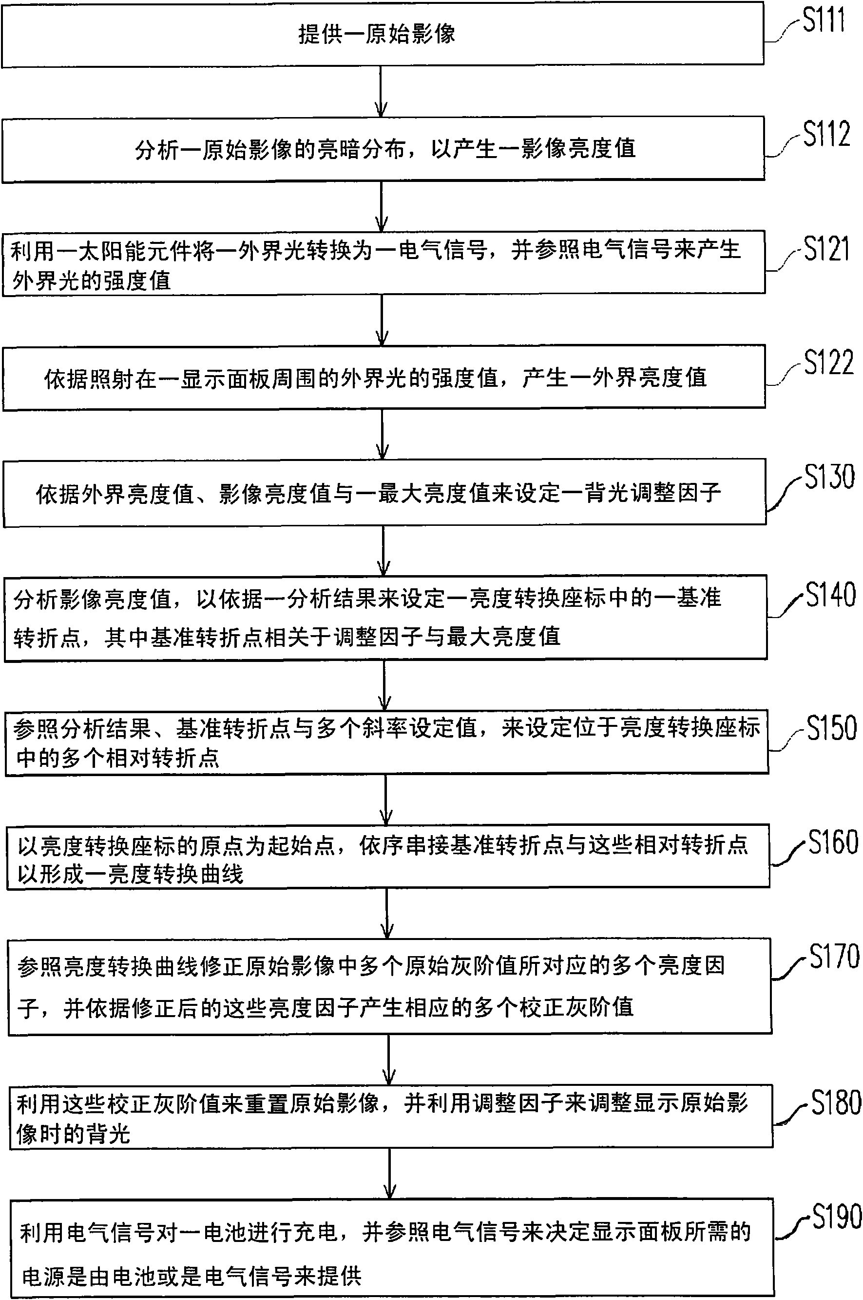
[0078] figure 1 Shown is a flow chart of the image display method according to the first embodiment of the present invention. The image display method described in this embodiment is suitable for a transmissive display panel. Please refer to figure 1 , first, in step S111, an original image is provided. Next, in step S112, the brightness and darkness distribution of the original image is analyzed, and an image brightness value is generated accordingly. Accordingly, the brightness of the original image can be measured with reference to the image brightness value.
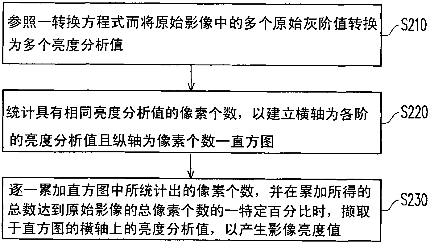
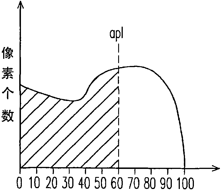
[0079] for example, figure 2 Shown is a detailed flow chart for explaining step S112. Here, it is assumed that the original image is composed of a plurality of pixels, and each pixel includes three sub-pixels. In addition, in the process of using these pixels to form an original image, each pixel corresponds to an original grayscale value, and each original grayscale value is formed by color mixing the sub-gra...
no. 2 example
[0147] Figure 14 Shown is a flow chart of an image display method according to a second embodiment of the present invention. The image display method described in this embodiment is suitable for a transflective display panel. Please refer to figure 1 and Figure 14 , the main difference between the second embodiment and the first embodiment lies in the detailed flow of step S122' and step S130'.
[0148] Specifically, similar to the first embodiment, this embodiment uses an original image provided in step S111 to perform the image analysis shown in step S112 to obtain an image brightness related to the brightness of the original image value. In addition, in this embodiment, in steps S121 and S122', the electrical signal converted by the solar element is used to generate an external brightness value related to the intensity value of the external light. Thereby, a backlight adjustment factor can be set by using the external brightness value, the image brightness value and ...
no. 3 example
[0164] Figure 16Shown is a flowchart of an image display method according to a third embodiment of the present invention. Wherein, the image display method described in this embodiment is suitable for a transmissive display panel or a transflective display panel. Please refer to figure 1 and Figure 16 The main difference between the third embodiment and the first embodiment lies in the newly added detailed processes of steps S1601 to S1603 and steps S122" and S130".
[0165] Specifically, similar to the first embodiment, this embodiment uses an original image provided in step S111 to perform the image analysis shown in step S112 to obtain an image brightness related to the brightness of the original image value. In addition, in this embodiment, in steps S121 and S122", the electrical signal converted by the solar element is used to generate an external brightness value related to the intensity value of the external light. Thereby, the external brightness can be utilized ...
PUM
 Abstract
Description
Claims
Application Information