

Vacuum insulation oil impregnating device and method thereof
A technology of vacuum insulation and impregnation device, applied in insulators, coil manufacturing, electrical components and other directions, can solve the problems of difficulty in ensuring vacuum degree, reduction of vacuum degree of oil immersion tank, generation of oil foam, etc., to ensure accuracy and improve processing effect. Effect
Active Publication Date: 2011-01-19
CHINA ELECTRIC POWER RES INST +1
View PDF5 Cites 20 Cited by
- Summary
- Abstract
- Description
- Claims
- Application Information
AI Technical Summary
Problems solved by technology
Chinese patent application 200810069818.3 discloses a differential pressure multifunctional vacuum oil immersion equipment, including a vacuum tank, an oil tank and a vacuum pump. The oil valve and the vacuum pump are connected to the vacuum tank through the intake and exhaust pipes. The vacuum tank outlet check valve is installed on the intake and exhaust pipes. The vacuum tank is equipped with a vacuum tank heating device. The vacuum tank is sealed during use, which can realize insulation The process of vacuum drying and oil immersion of materials, and the use of air pressure difference and gravity to realize the convenient recycling of oil, its disadvantages are: the oil storage cylinder of the device is located under the oil immersion cylinder, and a high pressure difference is required when working. The oil in the oil storage barrel is sucked into the oil immersion cylinder, so it is more difficult for the device to ensure the vacuum degree during operation
Moreover, the patent relies on valves to control the connection between the oil storage cylinder and the oil immersion cylinder, and the oil storage cylinder cannot withstand vacuum pressure. After the connection valve is opened, the oil immersion cylinder is in a vacuum state and the upper part of the oil storage cylinder is in an atmospheric pressure environment, thus forming a nearly 1 Atmospheric pressure injects oil into the oil immersion cylinder, which will cause a sharp drop in vacuum and produce a large amount of oil foam, which will affect the impregnation effect.
According to the summary, when the traditional air pressure difference method is used for oil filling, the vacuum degree in the oil immersion tank will inevitably be reduced, and oil foam may be generated, which cannot guarantee the oil immersion requirements of the cardboard under vacuum, thereby affecting the oil immersion effect. Insulating cardboard The evaporation of water and the overflow of air bubbles are affected, which in turn affects the dielectric loss value and other parameters of the insulating cardboard. Therefore, it is impossible to guarantee the smooth progress of the test, and the impact on the test results is even more difficult to evaluate.
Method used
View moreImage
Smart ImageViewing Examples

Examples
Embodiment Construction
Login to View More PUM
 Abstract
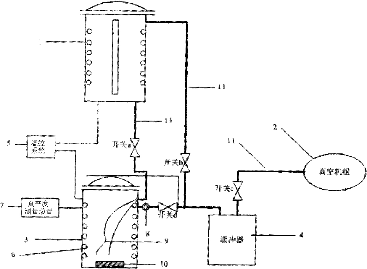
The invention provides a vacuum insulation oil impregnation device and a method thereof. Vacuum oil impregnation is carried out by a liquid level difference method; an oil storage tank is higher than an oil impregnation tank; when the vacuum oil impregnation device works, the vacuum oil impregnation device can fully evaporate the interior of a sample in a high-temperature ultimate vacuum approaching state; after the dryness meets the requirement, a valve for connecting the oil storage tank and the oil impregnation tank is opened; and because the two tanks are all positioned in the ultimate vacuum approaching state, the insulating oil of the oil storage tank automatically flows into the oil impregnation tank under the action of gravity. The device and the method have the advantages that: the defects of the conventional air pressure difference method are avoided, the vacuum degree of the two tanks is kept unchanged, extra gas cannot enter an insulating carton and the transformer oil, oil foam cannot be generated in the oil impregnation process, the moisture inside the solid insulating material is ensured to be fully evaporated, a cavity inside the solid insulating material can be fully filled with a liquid insulating material, the insulating material treatment effect is improved, and the accuracy of the subsequent test conclusion is ensured.
Description
technical field The invention relates to the technical field of high voltage and insulation, in particular to an oil-based vacuum insulation impregnation device and method thereof, mainly used for drying treatment of high-voltage insulation materials, and injecting transformer oil and varnish in a vacuum state after vacuum drying is completed. Filling the inner cavity of the insulating material with insulating liquid such as transformer oil and varnish can greatly improve the insulating performance of the material. Background technique Oil-paper insulation is the most common internal insulation structure for large-scale, high-voltage power equipment, and has been widely used in large-scale power equipment. There are cavities and air gaps in the insulating cardboard, which are the main reasons for the partial discharge and deterioration of the insulation. In addition, the moisture content in the untreated cardboard is much higher than the standard requirement value, which dir...
Claims
Login to View More Application Information
Patent Timeline
 Patent Type & AuthorityApplications(China)
IPC IPC(8): H01B19/02H01F41/12
Inventor李博程涣超李金忠李光范孙倩邓俊宇徐会雨
OwnerCHINA ELECTRIC POWER RES INST