
Golf head

A golf head and club head technology, which is applied to golf balls, golf clubs, rackets, etc., can solve the problems of short staying time, increased ball-biting performance of the hitting panel, and unsatisfactory ball-controlling effects, etc.

Inactive Publication Date: 2011-03-30
PERFORMAX GOLF & COMPOSITE
View PDF0 Cites 3 Cited by
  • Summary
  • Abstract
  • Description
  • Claims
  • Application Information

AI Technical Summary

Problems solved by technology

However, since this kind of hitting surface will not be deformed, the time for the ball to stay on the hitting panel is short, so the power to make the ball reverse is entirely from the direct friction between the line groove and the ball, and the sideways friction between the line groove and the ball surface is used to The friction causes the ball to reverse. The result of a 5-iron shot with a mechanical arm at a speed of 75mph can make the ball produce about 5800rpm, the total distance is 184 yards, and the rolling distance is 9 yards. Although this structure has its basic effect However, the effect on ball control is still not ideal
[0003] Another example is the "hidden line groove structure on the hitting face of a golf club head" disclosed in Taiwan Patent Publication No. 439513. Although this case reveals the concept of the hidden line groove, the deformation of the hitting panel increases the ball's ability to hit the ball. The time spent on the panel, but the batting panel in this case did not match with the hidden line groove for structural disclosure or setting, so the elastic effect of the deformable batting panel can not be multiplied after deformation , and cooperate with the outer line groove to increase the ball bite of the batting panel

Method used


Image

  • Golf head
  • Golf head
  • Golf head

Examples


Embodiment Construction

[0019] The structure and effect of the present invention will be described in detail by citing the following embodiments in conjunction with the accompanying drawings.

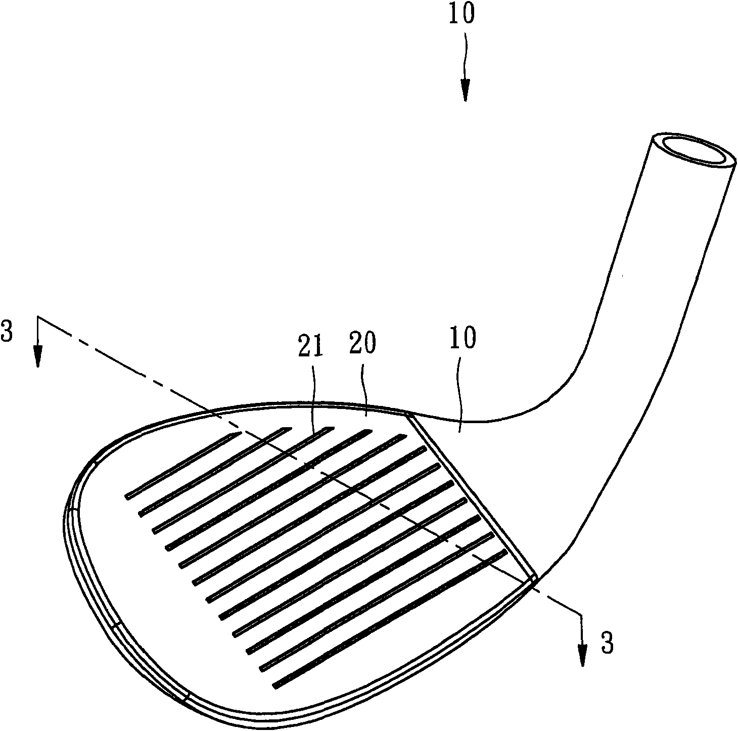
[0020] Such as figure 1 and Figure 5 As shown, the present invention is implemented in the state of the iron club head. Of course, the same structure can also be applied to the wood club head or other club heads. The golf head provided by the present invention includes:

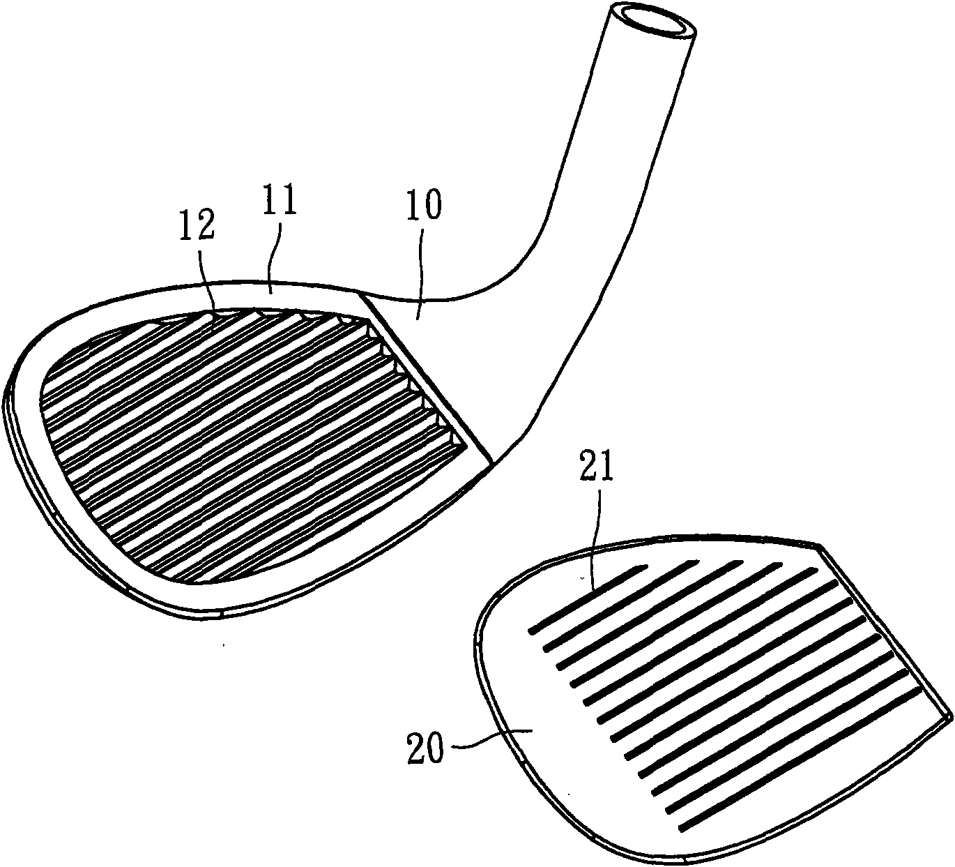
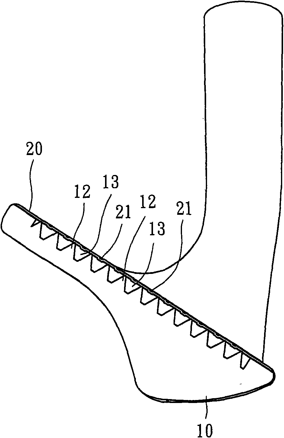
[0021] Such as Figure 1 to Figure 5 As shown, a club head body 10, the club head body 10 is provided with a groove 11 at the position of the ball striking surface, and a plurality of supporting parts 12 are protruded on the bottom wall of the groove 11 to form a plurality of inner line grooves 13 (such as image 3 shown), each support portion 12 can be arranged in a horizontal arrangement, and can also be arranged in a vertical or different angle arrangement (such as Figure 5 shown), and the distance between two adjacent supporting part...


PUM


Abstract

The invention relates to a golf head, which comprises a club head body and a batting panel, wherein the club head body is provided with a groove at a batting surface position, and the bottom wall of the groove is convexly provided with a plurality of supporting parts to form a plurality of inner line channels; and the right side of the batting panel is provided with a plurality of outer line channels, the batting panel is embedded and fixed at the groove position of the club head body, and the back of the batting panel is propped against the top of each supporting part. By using the structure of double-layer line channels, the batting panel can produce little deformation during batting, and the reversing speed of the batted golf can be increased.

Description

technical field [0001] The present invention relates to golf clubs, in particular to a golf head. Background technique [0002] Generally, concave line grooves are set on the hitting surface of the golf club head. The main purpose of setting the line grooves is to make the hit ball reverse (back spin), which can reduce the rolling distance of the ball after landing. to improve ball control. However, since this kind of hitting surface will not be deformed, the time for the ball to stay on the hitting panel is short, so the power to make the ball reverse is entirely from the direct friction between the line groove and the ball, and the sideways friction between the line groove and the ball surface is used to The friction causes the ball to reverse. The result of a 5-iron shot with a mechanical arm at a speed of 75mph can make the ball produce about 5800rpm, the total distance is 184 yards, and the rolling distance is 9 yards. Although this structure has its basic effect Howe...

Claims


Application Information

Patent Timeline
IPC IPC(8): A63B53/04A63B102/32
Inventor 谢渊源詹昆学杜志成
Owner PERFORMAX GOLF & COMPOSITE
Learn More