Photocatalytic oxidation flue gas desulfurization and denitration system of coal-fired power plant

A technology of photocatalytic oxidation and coal-fired power plants, which is applied in the interdisciplinary fields of energy engineering and environmental engineering, and can solve the problems of large construction investment, high operating cost, and large floor area

Inactive Publication Date: 2011-04-06
武汉慧邦环境工程技术有限公司
View PDF4 Cites 17 Cited by
  • Summary
  • Abstract
  • Description
  • Claims
  • Application Information

AI Technical Summary

Problems solved by technology

[0010] The purpose of the present invention is to overcome the disadvantages of desulfurization and denitrification in coal-fired power plants that need to be built separately for desulfurization and denitrification in the current technology, which requires a large area, large construction investment, complicated operation and maintenance, and high operating costs. At the same time, it makes up for the existing photocatalytic There are many defects in oxidative desulfurization and denitrification technology. To provide a coal-fired power plant photocatalytic oxidative desulfurization and denitrification system with small footprint, small construction investment, simple operation and maintenance, and low operating cost. Desulfurization can be realized simultaneously in a set of equipment (complete equipment) Denitrification with high removal efficiency and no secondary pollution

Method used


Image

  • Photocatalytic oxidation flue gas desulfurization and denitration system of coal-fired power plant
  • Photocatalytic oxidation flue gas desulfurization and denitration system of coal-fired power plant
  • Photocatalytic oxidation flue gas desulfurization and denitration system of coal-fired power plant

Examples


Embodiment approach

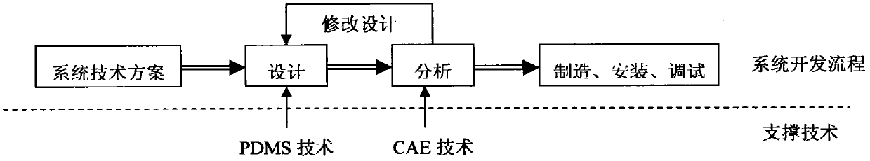
[0052] When applying the technical solution provided by the present invention to develop a complete set of equipment for the photocatalytic oxidation desulfurization and denitrification system in a coal-fired power plant, the main task is to build a PDMS-CAE collaborative development platform, and the key point is to realize the PDMS (Plant Design Management System) and CAE (Computer Aided Engineering), the development process is as follows image 3 shown. After the development platform is built, the original parameters and intermediate parameters of the flue gas (determined by theoretical calculation and experiments) are input to obtain the purchase list (direct outsourcing part), equipment manufacturing drawings and construction installation drawings. The PDMS-CAE collaborative development platform can realize the parallel collaborative design of processes, instruments, equipment, construction and installation, electrical and control, etc., and provide a common collaboration...


PUM


Abstract

The invention relates to a photocatalytic oxidation flue gas desulfurization and denitration system of a coal-fired power plant, which belongs to the cross field of energy source engineering and environmental engineering, and is applied to simultaneous flue gas desulfurization and denitration of the coal-fired power plant. The process route of the system comprises the following steps of: preparing oxygen with more than 90% of purity by using an oxygenator, and introducing the prepared oxygen into a photo-catalyzing reaction tower for fully reacting to produce an oxidizing material as a main component; simultaneously introducing the oxidizing material and flue gas (after dust extraction) into an oxidizing reaction tower, oxidizing SO2 in the flue gas by the oxidizing material into a final product SO3, and oxidizing NO and NO2 by the oxidizing material into a final product NO3; absorbing SO3 and NO3 in the flue gas after oxidizing reaction when passing through an absorption tower; and completing the simultaneous flue gas desulfurization and denitration process. During desorbing, the obtained by-product, namely nitrate-sulfur acid is collected by a storage tank and is an industrial chemical with wide uses. The system simultaneously realizes desulfurization and denitration in one set of device (complete equipment) and has high removal efficiency and no secondary pollution.

Description

Technical field: [0001] The invention belongs to the intersection field of energy engineering and environmental engineering, and in particular relates to a desulfurization and denitrification system for photocatalytic oxidation flue gas of a coal-fired power plant. Background technique: [0002] Coal-burning pollution is one of the main sources of air pollution in my country. In the primary energy consumption and its composition, coal-fired accounts for about 70%. The largest coal-consuming households in my country are mainly coal-fired power plants. Sulfur dioxide emissions account for about 55% of total industrial emissions, and nitrogen oxide emissions account for about 43% of total industrial emissions. It is estimated that by 2020, my country's northeast, north, southeast regions and the Sichuan Basin SO 2 Emissions reached 30.6 million tons, NO x Emissions amounted to 26.6 million tons. Therefore, reducing and controlling coal combustion, especially coal-fired power ...

Claims


Application Information

Patent Timeline
Patent Type & Authority Applications(China)
IPC IPC(8): B01D53/86B01D53/76B01D53/60
CPCY02A50/20
Inventor 张杰
Owner 武汉慧邦环境工程技术有限公司
Why Eureka
Try Eureka