Clip

一种卡夹、条带的技术,应用在螺纹紧固件、服饰、连接构件等方向,能够解决卡夹插入操作工作效率减小等问题

Inactive Publication Date: 2011-04-27
DAIWA KASEI IND CO LTD
View PDF8 Cites 10 Cited by
  • Summary
  • Abstract
  • Description
  • Claims
  • Application Information

AI Technical Summary

Problems solved by technology

As a result, the work efficiency of the card holder insertion operation may decrease

Method used


Image

  • Clip
  • Clip
  • Clip

Examples


Embodiment Construction

[0019] will refer to Figures 1 to 6 Detailed representative embodiments of the present invention are described.

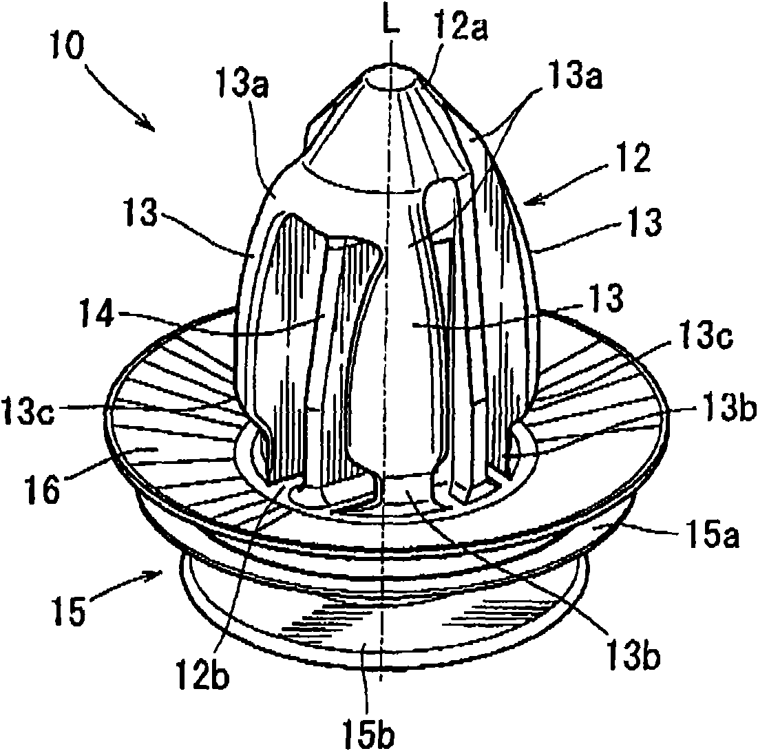
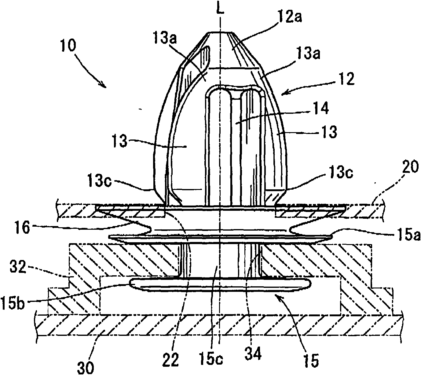
[0020] Such as figure 1 and 2 As shown, a representative clip 10 may be integrally formed as a unit by molding of resin. The clip 10 may preferably include an upper anchor portion 12 , a lower connection portion 15 and a disc portion 16 between the anchor portion 12 and the connection portion 15 .

[0021] The anchor portion 12 may preferably include a distal portion 12a and a proximal portion 12b connected to the disc portion 16 . The distal end portion 12a of the anchor portion 12 is formed as a tapered solid portion (block). Conversely, the proximal portion 12b of the anchoring portion 12 is sufficiently rigid to function as the base portion of the clip 10 .

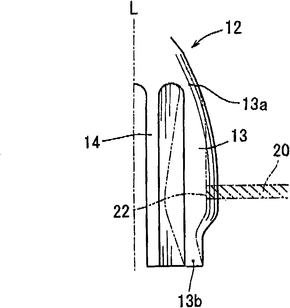
[0022] The anchoring portion 12 may also comprise a plurality (four in the described embodiment) of vertical flexible strips 13 and at least one (two in the described embodiment) vertical support st...


PUM


Abstract

A clip may include an anchor portion having a plurality of flexible strips and at least one support strip. Each of the flexible strips is integrally connected to the at least one support strip only via a connecting portion corresponding to a distal end portion of the anchor portion and a connecting portion corresponding to a proximal end portion of the anchor portion. When the anchor portion is pushed into an insertion hole formed in a subject member, the anchor portion is inserted into the insertion hole while each of the flexible strips are flexed toward a longitudinal axis of the anchor portion. Each of the flexible strips is formed such that the difference between a second moment of area of the anchor distal end side connecting portion and a second moment of area of the anchor proximal end side connecting portion is 0-15%.

Description

[0001] This application claims priority from Japanese Patent Application No. 2009-226609, the contents of which are incorporated by reference into this application. technical field [0002] The present invention relates to a clip that can be attached to a body part, such as a vehicle body. More particularly, the present invention relates to a clip that can be attached to a body part by inserting its anchor portion into an insertion hole formed in the body part. Background technique [0003] A clip of this type is already known and taught, for example, by Japanese Laid-Open Patent Document No. 2002-81422. The clip includes an anchor portion (engagement portion) inserted into an insertion hole formed in the body part. The anchor portion has a plurality of flexible strips. When the anchoring portion is pushed into the insertion hole, the anchoring portion is inserted into the insertion hole, while each flexible strip bends inwardly, so that the protruding portion (shoulder po...

Claims


Application Information

Patent Timeline
Patent Type & Authority Applications(China)
IPC IPC(8): F16B19/00
CPCF16B21/086Y10T24/309Y10T24/44Y10T24/44026
Inventor 岩原利夫藤井和树
Owner DAIWA KASEI IND CO LTD
Why Eureka
Try Eureka