Method for transmitting detection signal by using user equipment (UE), UE and base station

A technology for detecting signals and user equipment, applied to the shaping network in the transmitter/receiver, using the return channel for error prevention/detection, space transmit diversity, etc., can solve the problem of low detection accuracy and increase the complexity of designing detection signals , Insufficient analysis of the detection environment and other problems, to achieve the effect of improving the detection accuracy

Inactive Publication Date: 2011-05-25
南通市通州区新志浩实业有限公司
View PDF3 Cites 17 Cited by
  • Summary
  • Abstract
  • Description
  • Claims
  • Application Information

AI Technical Summary

Problems solved by technology

Taking the Long Term Evolution (LTE, Long Term Evolution) system as an example, the Sounding Reference Signal (SRS, Sounding Reference Signal) in the LTE system is a sounding signal used for the base station to obtain bandwidth channel information. In the current LTE system, the Up to 2 antennas can be configured on the UE side, and the UE only needs to send SRS on the 2 antennas in turn, and the base station can learn the uplink broadband channel information through multiple transmissions; and with the continuous evolution of technology, in the future LTE-Advanced In the system, the number of configurable antennas on the UE side will also increase, for example up to 4, and more advanced technologies can be applied in the LTE-Advanced system, such as precoding technology, which increases the design The complexity of probing the signal
[0008] To sum up, for the scenario where the user equipment UE has multiple antennas, that is, two or more antennas are used to send sounding signals, in order to cope with the development of technology, it is necessary to provide a more flexible way of sending sounding signals to solve the problems existing in the current technology. The technical problem of low detection accuracy caused by insufficient analysis of the detection environment

Method used


Image

  • Method for transmitting detection signal by using user equipment (UE), UE and base station
  • Method for transmitting detection signal by using user equipment (UE), UE and base station
  • Method for transmitting detection signal by using user equipment (UE), UE and base station

Examples


no. 2 example

[0039] In the second embodiment, this embodiment provides a method for a base station to instruct a UE to send a sounding signal by describing a process on the base station side.

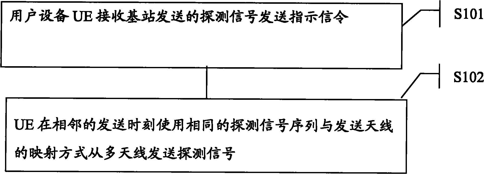
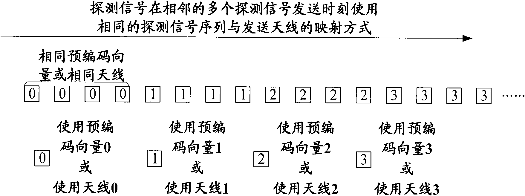
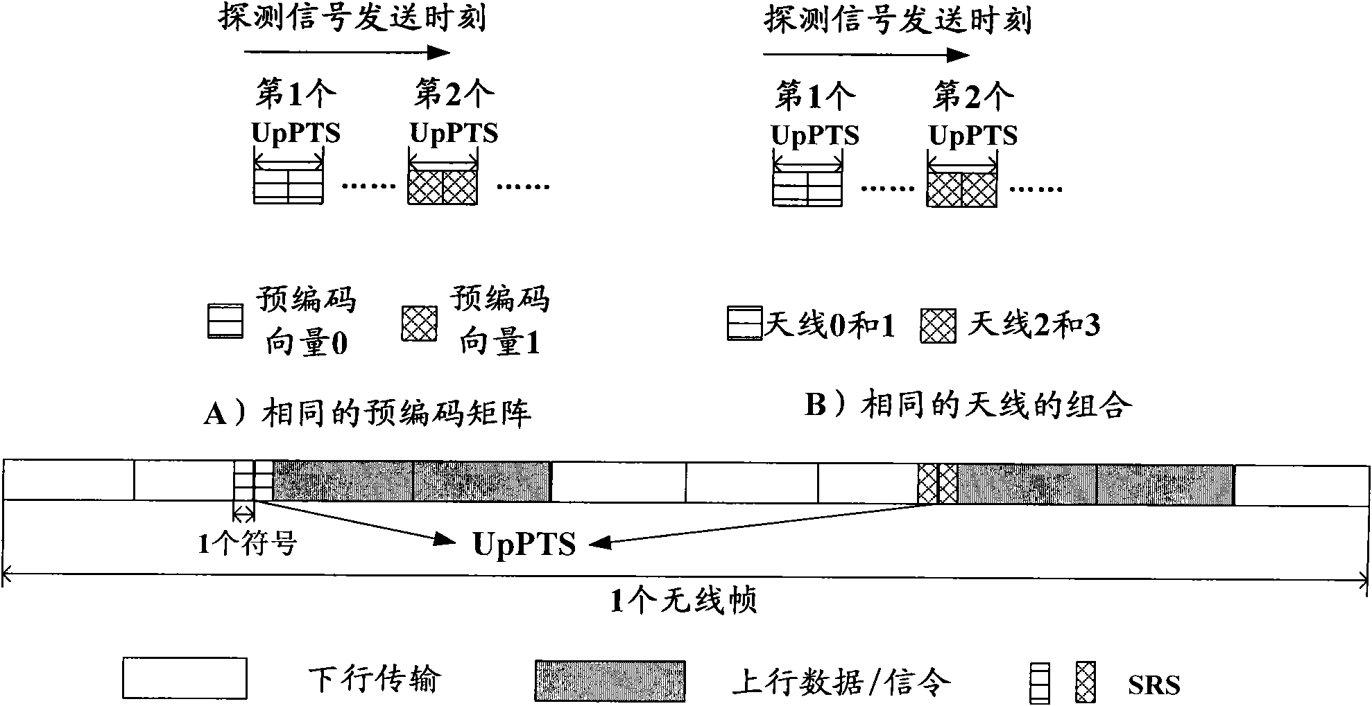
[0040] Specifically, the method includes that the base station sends a sounding signal transmission indication signaling to the user equipment UE, where the sounding signal transmission indication signaling includes a mapping manner between a sounding signal sequence and a transmitting antenna, and is used to instruct the UE to transmit the sounding signal in an adjacent The same or different mapping manners between the sounding signal sequences and the sending antennas are used at all times to send sounding signals from multiple antennas.

[0041] Wherein, the sending time, the sending period, the sounding signal, the mapping manner of the sounding signal sequence and the sending antenna have the same meaning as the same concept in the first embodiment. The flow is also corresponding, because this ...


PUM


Abstract

The invention provides a method by which the detection accuracy of a detection signal can be improved aiming at the condition that user equipment (UE) transmits the detection signal by using a plurality of antennas and which can be flexibly used for the UE under different environments. The method comprises the following steps that: the UE receives a detection signal transmission instruction signaling which is transmitted by a base station, wherein the detection signal transmission instruction signaling comprises a detection signal transmission moment of the UE; and in a set detection signal transmission time interval or a detection signal transmission time interval which is noticed by the base station, the UE transmits the detection signal from the plurality of antennas by using the same detection signal sequence in a transmitting antenna mapping mode at transmission moments which are indicated by adjacent base stations. Corresponding to the method implemented on a UE side, the invention also correspondingly provides a method on a base station side and corresponding user equipment and base station.

Description

technical field [0001] The invention relates to the communication field, and is specifically applicable to the technical field of detecting signal transmission for realizing channel detection. Background technique [0002] In the existing technology, the base station needs to complete the scheduling of the user equipment UE by knowing the broadband channel information, and the sounding signal is important information for the base station to know the uplink broadband channel information, so obtaining the sounding signal is an important part of information exchange between the base station and the user equipment . [0003] The following is the manner in which the base station obtains broadband channel information in the prior art: [0004] S001, the base station notifies the UE of information about resources used by the sounding signal through downlink signaling, where the information includes the sending time of the sounding signal, the sending frequency band, the sending an...

Claims


Application Information

Patent Timeline
Patent Type & Authority Applications(China)
IPC IPC(8): H04L1/06H04L1/00H04L1/18H04L25/03H04B7/06
Inventor 周明宇任晓涛万蕾
Owner 南通市通州区新志浩实业有限公司
Why Eureka
Try Eureka