Array antenna

An array antenna and array technology, which is applied in the field of antennas, can solve the problems of poor axial ratio at low elevation angles and narrow antenna bandwidth, and achieve the effects of good axial ratio bandwidth, good grounding, and good low elevation gain.

Inactive Publication Date: 2012-08-29
HARXON CORP
View PDF1 Cites 0 Cited by
  • Summary
  • Abstract
  • Description
  • Claims
  • Application Information

AI Technical Summary

Problems solved by technology

[0003] The object of the present invention is to provide an array antenna to solve the problems of the existing array antennas with narrow bandwidth and low elevation angle axis ratio

Method used


Image

  • Array antenna
  • Array antenna
  • Array antenna

Examples


Embodiment Construction

[0026] The technical solutions of the present invention are further described below with reference to the accompanying drawings and specific embodiments of the description.

[0027] It should be understood that the specific embodiments described herein are only used to explain the present invention, but not to limit the present invention.

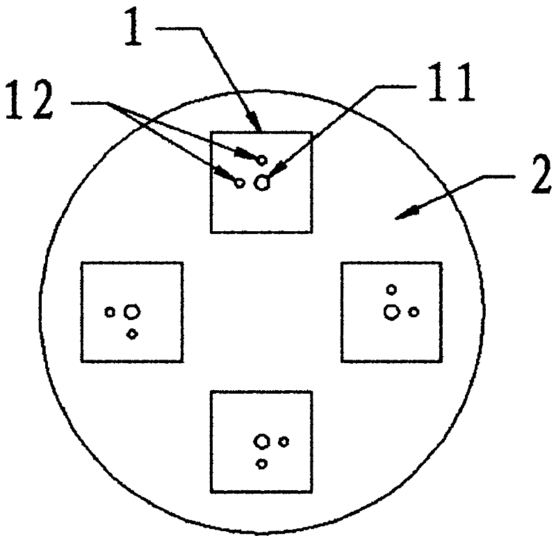
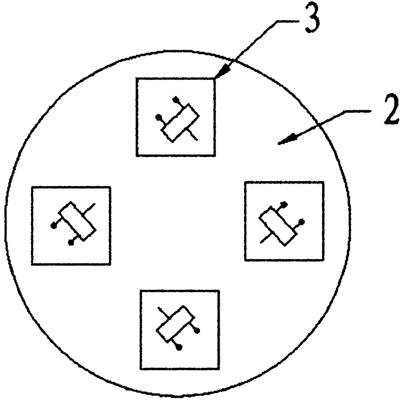
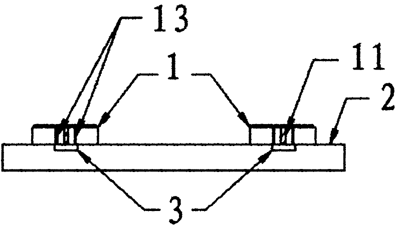
[0028] like figure 1 Shown is a schematic front view of the array antenna of the present invention when it has 4 microstrip antenna units; figure 2 ,Right now figure 1 A schematic diagram of the back of the array antenna. In this embodiment, the array antenna includes a microstrip antenna array, a reflector 2 and a phase-shifting feed network 3. The microstrip antenna array is composed of four microstrip antenna units 1 and four microstrip antenna units. The strip antenna unit 1 is centered on the center of the reflector 2, and is equally spaced on the front of the reflector 2. The isolation of adjacent microstrip antenna units 1 is grea...


PUM


Abstract

The invention relates to an array antenna which comprises a microstrip antenna array, a baffle board and a phase-shift feed network, wherein the microstrip antenna array is located on the front of the baffle board and the phase-shift feed network is located on the back of the baffle board. The array antenna provided by the invention has a compact structure, strong anti-jamming capability, favorable axial ratio bandwidth and low elevation gain.

Description

technical field [0001] The present invention relates to the field of antennas, in particular to an array antenna. Background technique [0002] With the continuous development of satellite navigation and measurement technology, satellite positioning systems have also been widely used. At present, many countries in the world have established their own satellite positioning systems, such as China's Beidou satellite navigation system, the United States' Global Positioning System (GPS), and Russia's Global Navigation Satellite System (GLONASS). ) and the European Galileo satellite positioning and navigation system. The satellite signal of the satellite navigation system represented by GPS is very weak and is easily affected by external radio frequency interference. Therefore, the anti-interference performance of the antenna of the satellite signal receiving device is relatively high. If the anti-interference ability of the antenna of the receiving device is not enough, In seve...

Claims


Application Information

Patent Timeline
Patent Type & Authority Patents(China)
IPC IPC(8): H01Q21/00H01Q23/00
Inventor 黄毅王春华
Owner HARXON CORP
Why Eureka
Try Eureka