

Vehicle-collision simulation testing apparatus
A simulation test, motor vehicle technology, applied in the direction of measuring device, vehicle test, vehicle impact test, etc., to achieve the effect of simple structure
- Summary
- Abstract
- Description
- Claims
- Application Information
AI Technical Summary
Problems solved by technology
Method used
Image

Examples
Embodiment 1
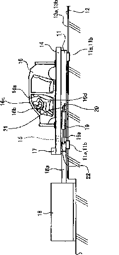
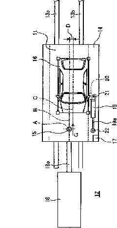
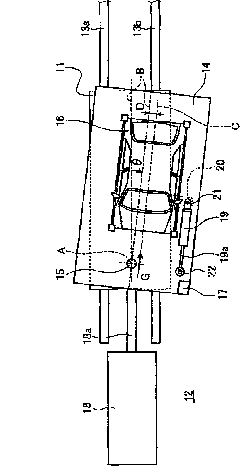
[0057] figure 1 It is a side view showing the automobile collision simulation test device of Embodiment 1 of the present invention, figure 2 It is a plan view showing the vehicle collision simulation test device of Example 1, image 3 It is a plan view showing the operation of the vehicle collision simulation test device of the first embodiment.
[0058] In the motor vehicle collision simulation test device of embodiment 1, such as figure 1 and figure 2 Shown, the tackle 11 as a platform is a frame member with a prescribed thickness, and is in the front-back direction when viewed from above (in figure 1 and figure 2 A rectangular shape long in the left-right direction in the middle. A pair of left and right rails 13a, 13b with a predetermined interval are attached to the floor 12 in the front-rear direction, and the trolley 11 is movably supported by sliders 11a, 11b fixed on the lower surface along the rails 13a, 13b.
[0059] The deflection block 14 is the same as t...
Embodiment 2
[0081] Figure 4 It is a plan view showing the vehicle collision simulation test apparatus according to the second embodiment of the present invention. In addition, members having the same functions as those described in the above-mentioned embodiments are given the same reference numerals and redundant descriptions are omitted.
[0082] In the motor vehicle collision simulation test device of embodiment 2, such as Figure 4 As shown, the trolley 11 is supported movably along a pair of left and right rails 13a and 13b attached to the floor 12 . The deflection tackle 14 is disposed above the tackle 11 , and its front portion is rotatably supported by the tackle 11 via a rotation shaft 15 , so that the deflection tackle 14 can turn horizontally around a rotation axis A. As shown in FIG. In addition, the test object 16 can be mounted on the upper surface of the deflection block 14 with a predetermined offset amount D. FIG.
[0083] In addition, in the deflection block 14, an e...
Embodiment 3
[0091] Figure 5 It is a side view showing the vehicle collision simulation test apparatus according to the third embodiment of the present invention. In addition, components having the same functions as those described in the above-mentioned embodiments are assigned the same symbols and redundant descriptions are omitted.
[0092] In the motor vehicle collision simulation test device of embodiment 3, such as Figure 5 As shown, the trolley 11 is supported movably along a pair of left and right rails 13a and 13b attached to the floor 12 . The deflection tackle 14 is disposed above the tackle 11 , and its front portion is rotatably supported by the tackle 11 via a rotation shaft 15 , so that the deflection tackle 14 can turn horizontally about a rotation axis A. As shown in FIG. In addition, the test object 16 can be mounted on the upper surface of the deflection block 14 with a predetermined offset amount D. FIG. Furthermore, in the deflection block 14, an eccentric mass 17...
PUM
 Abstract
Description
Claims
Application Information