Screen floating device

A technology of floating devices and screens, applied in projection devices, optics, instruments, etc., can solve problems such as fragile edges and easy to affect the display quality of large screens, and achieve the effect of minimizing seams

Active Publication Date: 2011-11-16
南通光烁通信设备有限公司
View PDF5 Cites 5 Cited by
  • Summary
  • Abstract
  • Description
  • Claims
  • Application Information

AI Technical Summary

Problems solved by technology

This climate change will have an important impact on the multi-screen display device composed of multiple basic units, which will easily affect the display quality of the large screen. At the same time, there are also the following problems: the edge of a single basic unit is fragile during transportation

Method used


Image

  • Screen floating device
  • Screen floating device
  • Screen floating device

Examples


Embodiment 1

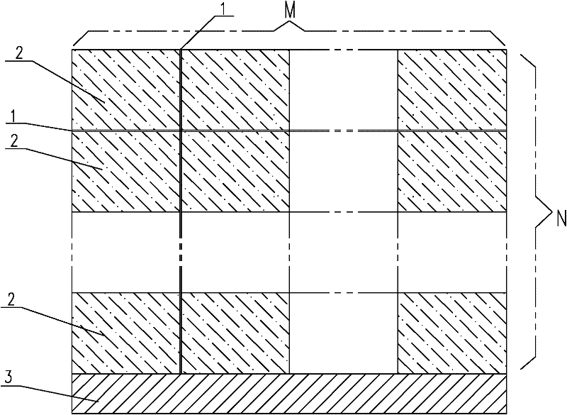
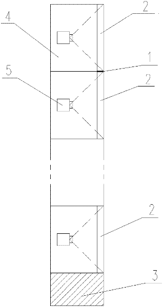
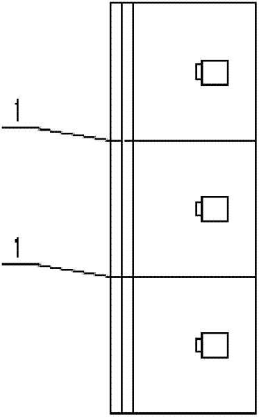
[0033] In this embodiment, a screen floating device has a structure such as Figure 4 or Figure 5 As shown, at least two support frames are included, and each support frame is respectively arranged on both sides of the rear projection box 6 and fixedly connected with both sides of the screen 2; each support frame is respectively provided with a rotating unit, and the rotating unit includes a rotating shaft 7 and a hinge hook 10 , the rotating shaft 7 is arranged on the rear projection box 6, and the hinge hook 10 is arranged on the rotating shaft 7 and is fixedly connected with the screen 2.

[0034] Such as Figure 7 As shown, the hinge hook 10 includes a fixed block and a hook portion, the fixed block and the hook portion are connected through a hinge shaft, the hook portion is fixedly connected with the rotating shaft, and the fixed block is fixedly connected with the screen.

[0035] The upper and lower ends of the rotating shaft 7 are respectively provided with hinge h...

Embodiment 2

[0038] In this embodiment, a screen floating device has a structure such as Figure 4 or Figure 5 As shown, at least two support frames are included, and each support frame is respectively arranged on both sides of the rear projection box 6 and fixedly connected with both sides of the screen 2; each support frame is respectively provided with a rotating unit, and the rotating unit includes a rotating shaft 7 and a hinge hook 10 , the rotating shaft 7 is arranged on the rear projection box 6, and the hinge hook 10 is arranged on the rotating shaft 7 and is fixedly connected with the screen 2.

[0039] Such as Figure 7 As shown, the hinge hook 10 includes a fixed block and a hook portion, the fixed block and the hook portion are connected through a hinge shaft, the hook portion is fixedly connected with the rotating shaft, and the fixed block is fixedly connected with the screen.

[0040] The upper and lower ends of the rotating shaft 7 are respectively provided with hinge h...

Embodiment 3

[0046] In this embodiment, a screen floating device has a structure such as Figure 4 or Figure 5 As shown, at least two support frames are included, and each support frame is respectively arranged on both sides of the rear projection box 6 and fixedly connected with both sides of the screen 2; each support frame is respectively provided with a rotating unit, and the rotating unit includes a rotating shaft 7 and a hinge hook 10 , the rotating shaft 7 is arranged on the rear projection box 6, and the hinge hook 10 is arranged on the rotating shaft 7 and is fixedly connected with the screen 2.

[0047] Such as Figure 7 As shown, the hinge hook 10 includes a fixed block and a hook portion, the fixed block and the hook portion are connected through a hinge shaft, the hook portion is fixedly connected with the rotating shaft, and the fixed block is fixedly connected with the screen.

[0048] The upper and lower ends of the rotating shaft 7 are respectively provided with hinge h...


PUM


Abstract

The invention discloses a screen floating device which comprises at least two supporting frames, and the supporting frames are respectively arranged at the two sides of a back-projecting box and fixedly connected with the two sides of a screen; and the supporting frames are respectively provided with a rotating unit, the rotating unit comprises a rotating shaft and a hook, the rotating shaft is arranged on the back-projecting box, and the hook is arranged at the rotating shaft and fixedly connected with the screen. By using the screen floating device disclosed by the invention, two adjacent screens can be mutually tightly combined, so that the minimization of an edge joint between the screens is realized, and then the effect that the edge joint is less than 0.5 mm is achieved. When pluralities of screens are fixed together by using spring nails for clamping, the situation that the edge joints are always minimized can be ensured without being affected by manufacturing tolerances or climatic changes.

Description

technical field [0001] The invention relates to the technical field of screen assembling, in particular to a screen floating device. Background technique [0002] In practical applications, the large screen of a multi-screen display device is generally assembled from many small screens or screens, such as figure 1 or figure 2 shown. figure 1 Shown is the front structure of a commonly used multi-screen display device, figure 2 Shown is the side structure of a commonly used multi-screen display device, which is composed of M screens in the horizontal direction and N screens in the vertical direction, and some may be equipped with a base at the bottom. In the figure, 1 is a seam, 2 is a single small screen, and 3 is a base. It can be seen from the figure that a support mechanism 4 and a projector 5 are respectively arranged behind the small screen, and the support mechanism 4 can be a corresponding to each small screen. One or more small screens correspond to one or a lar...

Claims


Application Information

Patent Timeline
Patent Type & Authority Applications(China)
IPC IPC(8): G03B21/56
Inventor 李选亮梁明浩邓启示胡日光罗振华
Owner 南通光烁通信设备有限公司
Why Eureka
Try Eureka