Beam-column connector and forming method, building frame structure and installation method

A beam-column connection and column technology, which is applied in building construction, construction, and building materials processing, etc., can solve problems such as beam or column dimension processing errors, ecological damage, and connection errors.

Inactive Publication Date: 2011-12-14
杨东佐
View PDF13 Cites 19 Cited by
  • Summary
  • Abstract
  • Description
  • Claims
  • Application Information

AI Technical Summary

Problems solved by technology

[0002] Existing cement brick mix, reinforced concrete house building and construction method thereof, owing to need to draw frame, cast concrete etc. with steel bar at the construction site, there is following shortcoming: the one is that its upright column pours and builds earlier, pours on upright column again Concrete floors are built, and the connection between the cement floor and the columns is mainly based on the steel bars on the columns and the cement floor. Since the columns and the cement floor are poured twice, the construction period is long, the labor intensity is high, the pollution is large, and the noise is large. The waste of construction raw materials is large; the second is that the relationship between two cement solids is only the bearing relationship of mechanical loads, and it is impossible to establish a truly integrated internal relationship, which has poor safety, poor earthquake resistance, and short service life; third, it is necessary to use cement, Wood and other building materials destroy ecology; Fourth, when houses are demolished, building materials cannot be reused, resulting in waste of resources and a large amount of construction waste that is difficult to handle; Fourth, due to the heavy weight of the frame structure of traditional cement buildings (high-rise buildings), The mechanical load of the foundation is very large. Once an earthquake shakes, the whole building becomes very fragile and dangerous, which is not conducive to earthquake resistance.
Second, there are many bolts and other fastening connections or welding connections on site, which will increase the difficulty of installation, reduce installation efficiency, and result in high labor and time costs for on-site construction.
The third is that the traditional building steel structure frame beams and columns or beams and beams are connected by bolt fastening or welding, and the respective connection ends must be designed and processed for matching connections. When standard profiles are used for beams or columns , the connecting ends must be designed and processed separately. When beams or columns do not use standard profiles, they need to be specially manufactured. Both methods cannot achieve mass standardized production. The cost is high, and beams or columns are prone to dimensional processing errors. The connection error makes it difficult for the already fragile connection position to bear the weight load of the building and the transmission of load force
Although in this technical scheme, the column member supports the lower column joint, the lower column joint supports the beam bucket, the beam bucket supports the upper column joint, the upper column joint supports the column member, and the beam bucket supports the beam bucket. It has a supporting function, and the gravity load of beams, columns, floors, etc. will not be transmitted to the welds and fasteners of the connecting nodes to bear; but the connection between the column members and the beams in this technical scheme needs to be connected through the upper column Joints, lower column joints, and beam buckets can only be realized. The disadvantages are: first, the combination of multiple parts can realize the connection between the column member and the beam, poor rigidity, and large assembly errors; Between the beam bucket and the beam bucket, the joint between the beam bucket and the upper column, and the joint between the upper column and the column member need to be fixed by self-pressing bolts or welding. There are many procedures and time-consuming installation. Many installation links will cause the verticality of the column member and its installation position It is difficult to adjust; in this technical scheme, the rigidity of multiple parts connecting column members and beams is poor, and the rigidity of the combination is even worse, which is not conducive to the bearing and transmission of heavy loads; the third is that the gravity of beams, columns, floors, etc. are transmitted in the end The connecting node is borne by the horizontal part of the beam bucket supported on the joint of the lower column, which will cause excessive stress concentration on the connecting node between the beam and the column or between the beam and the beam, so that the connecting node is poorly stressed and the connection is fragile, which will greatly Reduce the safety of the building frame structure and shorten the service life

Method used


Image

  • Beam-column connector and forming method, building frame structure and installation method
  • Beam-column connector and forming method, building frame structure and installation method
  • Beam-column connector and forming method, building frame structure and installation method

Examples


Embodiment 1

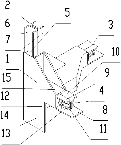
[0227] Such as figure 1 As shown, the beam-column connector is the bottom beam-column connector, including an integrally formed beam-column connector body 1, an upper column plug joint 2 that needs to be plugged and fixed with the end of the vertical column in the direction of the vertical horizontal plane, and two direct support A crossbeam parallel to the horizontal plane, a horizontal support joint 3 and a horizontal support joint 4 connected and fixed to the ends of the crossbeam.

[0228] A supporting column horizontal plane 5 directly supporting the column is provided above the beam-column connector body 1 . The upper column plug connector includes symmetrical U-shaped blocks 6 and 7 extending vertically upward from the horizontal plane of the supporting column, with openings facing both sides, and horizontally side by side. The gap between the U-shaped block 6 and the U-shaped block 7 forms an accommodating groove matched with the connection part of the I-shaped steel....

Embodiment 2

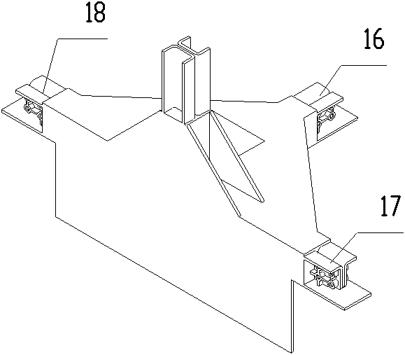
[0232] Such as figure 2 As shown, different from Embodiment 1, there are three horizontal support joints, namely, horizontal support joint 16, horizontal support joint 17, and horizontal support joint 18, and horizontal support joint 16, horizontal support joint 17, and horizontal support joint 18 are perpendicular to each other. , into a T-shape.

Embodiment 3

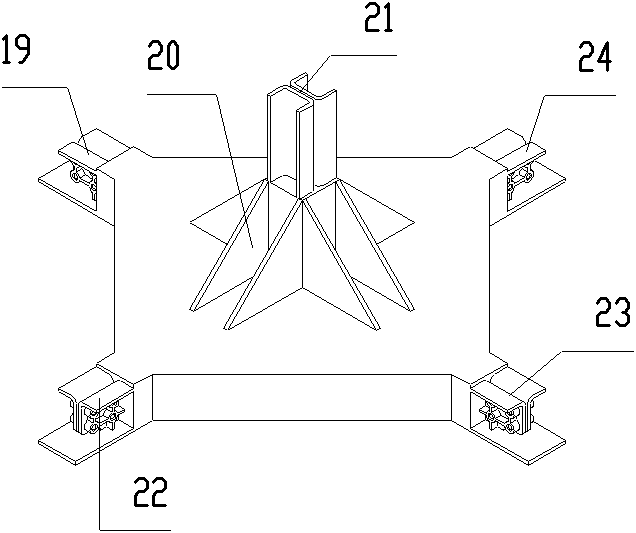
[0234] Such as image 3 As shown, the beam-column connector is a bottom beam-column connector, including an integrally formed beam-column connector body 20, an upper column plug joint 21 that needs to be plugged and fixed with the end of the vertical column in the direction of the vertical horizontal plane, four in ten The glyph directly supports the beam parallel to the horizontal plane, the horizontal support joint 22, the horizontal support joint 23, the horizontal support joint 24, and the horizontal support joint 19 connected with the end of the cross beam. The bottom surface of the beam-to-column connector body 20 is a plane. The structure of the upper column plug connector 21 and the four horizontal support connectors is the same as that of Embodiment 1.


PUM


Abstract

The invention discloses a beam and column connecting member which comprises an integrally-formed beam and column connecting member body, upright splicing heads and a horizontal support joint, wherein the beam and column connecting member is formed through casting; and a building frame structure comprises the beam and column connecting member, an upright spliced and fixed with the upright splicinghead, and a beam supported and fixed with the horizontal support joint. An installing method comprises the steps of: installing the upright spliced and fixed with the lower upright splicing head, installing the beam and column connecting member, and installing the beam. The invention has the advantages of greatly reducing connecting links of fastening connection or welding of bolts and the like, greatly reducing defects of poor stress and weak connection of connecting positions, caused when stress is excessively concentrated on beams and column or connecting positions among the beams, therebygreatly increasing installing efficiency and seismic resistance function, service life and use safety of a building frame structure. The beam and column connecting member can be massively pre-produced in a standardized manner.

Description

technical field [0001] The invention relates to a beam-column connector and a forming method, a building frame structure and an installation method of buildings, pavilions, booths, bridges and other buildings, in particular to a beam-column connector and a forming method and a frame of a steel structure of a building frame structure and installation method. Background technique [0002] Existing cement brick mix, reinforced concrete house building and construction method thereof, owing to need to draw frame, cast concrete etc. with steel bar at the construction site, there is following shortcoming: the one is that its upright column pours and builds earlier, pours on upright column again Concrete floors are built, and the connection between the cement floor and the columns is mainly based on the steel bars on the columns and the cement floor. Since the columns and the cement floor are poured twice, the construction period is long, the labor intensity is high, the pollution i...

Claims


Application Information

Patent Timeline
Patent Type & Authority Applications(China)
IPC IPC(8): E04B1/58E04B1/18E04G21/14
CPCE04B2001/249E04B2001/2421E04B1/24E04B2001/2451E04B2001/2472E04B2001/2457E04B2001/0092E04B2001/2448E04B2001/2433E04B2001/2406E04B2001/2463
Inventor 杨东佐
Owner 杨东佐
Why Eureka
Try Eureka