Bottom power taking self-locking electric bus battery box system capable of quickly changing battery

An electric bus and battery box technology, applied in electric vehicle charging technology, electric power device, power device and other directions, can solve the problems of deformation of the grasping mechanism, easy deformation of the battery box, and easy arcing at the plug connection of the power line, etc. Reliable locking effect

Active Publication Date: 2012-01-04
KUNMING SHIPBUILDING EQUIP
View PDF9 Cites 37 Cited by
  • Summary
  • Abstract
  • Description
  • Claims
  • Application Information

AI Technical Summary

Problems solved by technology

[0003] At present, the battery replacement in the market is difficult to be automated, and in the structural design of the battery quick change, there are over-positioning of the battery box, easy deformation of the battery box, easy arcing at the power line plug, and power line plug bumps in the electric bus. There are many defects such as easy bending or even breaking, and the design defect of over-positioning of the battery box also makes it difficult to automatically complete the locking and unlocking of the battery box
For example, a Chinese patent with the publication number CN101289056 discloses a quick-change electric vehicle battery box, which adopts a plug-type method of taking power from the rear end of the battery box, and the output terminal of the plug is rigid, and its locking and unlocking mechanism adopts Locking is achieved from the left and right sides of the battery box through the bolts of the lock tongue, so that when the power line of the battery box is not plugged in place, it is difficult for the lock tongue of the locking mechanism to be inserted into the lock holes on the left and right sides of the battery box, and when the electric bus During long-term turbulence, arcing will occur at the plug of the power line, which will cause welding between the plug and the socket. In addition, because the output terminal is rigid, it is very easy to bend, deform or even break during turbulence, which will cause battery damage. It is difficult to realize the automatic unlocking of the box when it is taken out; in addition, the drawer-type movement between the battery inner box and the outer box is realized by rolling the rollers in the upper and lower slideways, and there is point contact between the rollers and the slideways. During the bumpy process, the rollers can easily cause impact on the slideway and cause deformation of the battery box
The Chinese patent with the publication number CN101890901A discloses a quick-change mechanism for electric vehicle power batteries. The battery sliding mechanism used is connected by rolling balls arranged in the positioning seat to the bottom surface of the battery box. The contact between the balls and the bottom surface of the battery box is point contact. , the impact on the battery box during vehicle bumps will cause deformation of the battery box. The electrical connection interface and electrical connector used are also set on the rear end side of the battery box, and the insertion is completed when the battery box slides in. , the connector is also rigid, there will be arcing phenomenon during use, and the electrical connector will also bend and deform during the bumping process
In the 2010 Shanghai World Expo, the design of the quick-change battery box of the electric bus is also designed to take power from the rear end of the battery box with a plug, the rolling roller slides in, and the locking mechanism is from the left and right sides of the battery box through the electromagnetic During operation, due to the bumps of the vehicle, there are problems such as deformation of the power line plug joint, arcing, welding, and difficulty in automatically locking and unlocking.
[0004] In addition, the existing battery box grabbing method is to take out the inner battery box from the outer battery box by means of an electromagnetic chuck or a vacuum chuck. Since the battery box is heavy, the car body will drop due to the load during the battery box removal process. Floating occurs. At this time, the installation plane of the battery box of the electric bus is higher than the placement plane of the battery box on the battery grabbing device, so a bending moment will be generated at the electromagnetic chuck, and the grabbing mechanism at this time will bear the bending moment at the same time. and pulling force, it is easy to cause the deformation of the grabbing mechanism, which is due to the over-constraint of the battery box when the battery is picked up by an electromagnetic chuck or a vacuum chuck

Method used


Image

  • Bottom power taking self-locking electric bus battery box system capable of quickly changing battery
  • Bottom power taking self-locking electric bus battery box system capable of quickly changing battery
  • Bottom power taking self-locking electric bus battery box system capable of quickly changing battery

Examples


Embodiment Construction

[0048] The present invention will be further described below through the embodiments and in conjunction with the accompanying drawings.

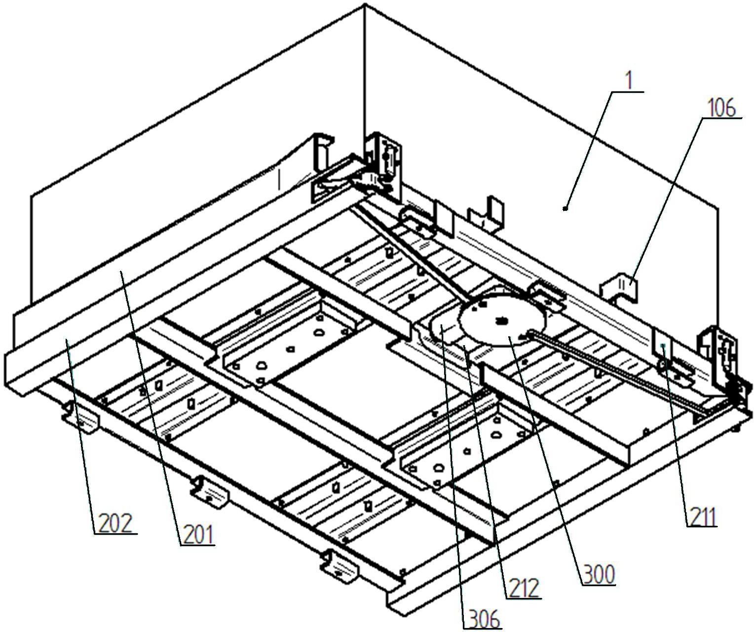
[0049] Such as figure 1 , figure 2 , image 3 As shown, the electric bus battery box system for self-locking and quick battery replacement of the electric bus at the bottom of the present invention includes a battery box 1, a tray 2 for carrying and positioning the battery box and installed on the electric bus, and a tray 2 for installing on the tray 2. The locking and unlocking device 3 for locking the battery box, the mobile device 4 for transporting the battery box, and the grabbing device 5 installed on the mobile device.

[0050] Such as Figure 4 , Figure 5 A. Figure 5 As shown in B, the battery box 1 includes a box body 101 containing battery cell modules and a battery management system, wedge-shaped locking blocks 102 installed on both sides of the front end of the box body, and two symmetrical openings located in the middle ...


PUM


Abstract

The invention discloses a bottom power taking self-locking electric bus battery box system capable of quickly changing a battery. The system comprises a battery box (1), a tray (2) used for bearing the battery box and arranged on an electric bus, mobile equipment (4) for conveying the battery box, and a grabbing device (5) arranged on the mobile equipment; and a battery box locking and unlocking device (3) is arranged on the tray. Through the system, automatic assembly of the battery box in the electric bus battery box system is realized, and the problems of over positioning, deformation of power wire connection pegs, breakage, arc discharge, welding, difficulty in automatically realizing unlocking due to impact of the battery box to a bolt of a locking mechanism in jolt and deformation of the battery box due to impact in jolt. The system is reasonable, reliable, simple and compact in structure, and can full-automatically, quickly and conveniently realize quick change of the power battery.

Description

technical field [0001] The invention belongs to the technical field of battery boxes for electric passenger cars, in particular to a battery box for electric passenger cars that can realize quick battery replacement. Background technique [0002] At present, electric buses in the field of new energy are developing in the direction of quick change, supplemented by plug-in charging, centralized charging, and unified distribution. The fast battery change solution can solve the problem of charging electric vehicles and make electric vehicles like ordinary vehicles. Like refueling a fuel vehicle, battery replacement can be completed in a short period of time, greatly reducing or even avoiding a series of impacts on electric vehicle travel due to insufficient battery power, which is conducive to the development and promotion of electric vehicles. [0003] At present, the battery replacement in the market is difficult to be automated, and in the structural design of the battery qui...

Claims


Application Information

Patent Timeline
Patent Type & Authority Applications(China)
IPC IPC(8): B60S5/06B60K1/04
CPCY02T90/124Y02T90/12
Inventor 李涛田华亭傅亚力张智勇
Owner KUNMING SHIPBUILDING EQUIP
Why Eureka
Try Eureka