
Simple special gear deburring machine
A simple and simple technology for deburring, applied to components with teeth, belts/chains/gears, gear teeth, etc., can solve problems such as low deburring efficiency, affecting product quality, and omissions, and achieves simple structure, wide application range, Guarantee the effect of processing quality
- Summary
- Abstract
- Description
- Claims
- Application Information
AI Technical Summary
Problems solved by technology
Method used
Image

Examples
Embodiment Construction
[0012] The present invention will be further described below in conjunction with the accompanying drawings.
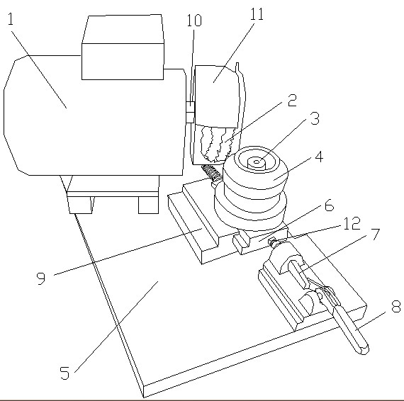
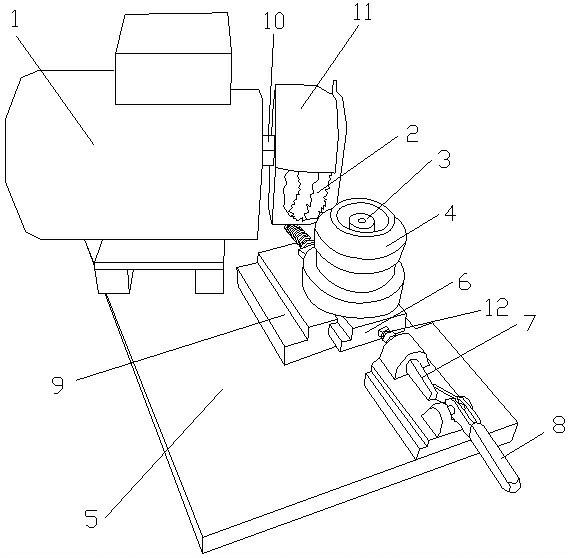
[0013] Such as figure 1 As shown, a simple special machine for deburring gears, including motor 1, deburring copper brush 2, bearing 3, positioning seat 4, base 5, guide rail 6, top tight connecting rod 7, handle 8, slide table 9, protective cover 11 and spring 12. On the base 5, a motor 1 is arranged, and the hair-removing copper brush 2 is installed on the output shaft 10 of the motor 1. On the base 5, the hair-removing copper brush 2 is provided with a slide table 9, and the slide table 9 is provided with a slideway, a guide rail 6 is installed in the slideway, a positioning seat 4 is arranged above the guide rail 6, a bearing 3 is arranged in the positioning seat 4, the positioning seat 4 on which the bearing 3 is installed can rotate, and a spring is installed on the end of the guide rail 6 opposite to the tight connecting rod 12. The position of the positioning...
PUM
 Abstract
Description
Claims
Application Information