

Blade device for static oiling machine
A technology of oiling machine and knife beam, applied in spraying device, liquid spraying equipment and other directions, can solve the problems of high fuel consumption, poor atomization effect, discontinuous and uniform spraying, etc., to ensure uniformity and avoid uneven effect.
- Summary
- Abstract
- Description
- Claims
- Application Information
AI Technical Summary
Problems solved by technology
Method used
Image

Examples
Embodiment 1
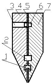
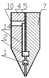
[0026] A knife beam device for an electrostatic oiler. The device as figure 1 and image 3 Shown, this device comprises knife beam left piece 4, plastic film 5 and knife beam right piece 7. The length, width and height of the knife beam left piece 4 are equal to the length, width and height of the knife beam right piece 7 respectively, and the knife beam left piece 4 and the knife beam right piece 7 are connected by bolts 9. A circulating oil tank 6 is provided on the upper part between the left piece 4 of the knife beam and the right piece 7 of the knife beam. Double "V" shaped oil groove 1. Be provided with plastic film 5 between knife beam left piece 4 and knife beam right piece 7, plastic film 5 is positioned at the rectangular oil tank 2 top except circulating oil tank 6. The gap between the left piece 4 of the knife beam and the right piece 7 of the knife beam below the rectangular oil tank 2 is 0.1 to 0.2 mm , The two ends of knife beam left piece 4 and knife bea...
Embodiment 2
[0035] A knife beam device for an electrostatic oiler. This device is except following technical parameter, all the other are with embodiment 1:
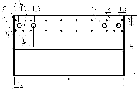
[0036] l 1 = 0.018~0.02 l ; l 2 = 0.030~0.035 l ; l 3 = 0.25~0.3 l 0 ; l 4 = 0.28~0.37 l 0 ; The centerline distance between rectangular oil groove 2 and double "V" shaped oil groove 1 is 5~6 mm .
[0037] The gap between the knife beam left piece 4 and the knife beam right piece 7 of this specific embodiment is controlled by the thickness of the plastic film 5, and its gap is 0.1 ~ 0.2 mm . The knife beam baffle plate 8 is to prevent the working oil from overflowing from both ends of the knife beam device; the circulating oil tank 6 can preheat the knife beam device and the oil when the ambient temperature is low, which is beneficial to the working oil Smooth flow; the width of the rectangular oil tank 2 is smaller than the diameters of the first working oil inlet 10 and the second working oil inlet 13, so th...
PUM
 Abstract
Description
Claims
Application Information