
eye measuring device

A measurement device and glare technology, which is applied to eye testing equipment, medical science, optometry, etc., can solve the problem that the time becomes longer, the inspector cannot easily judge the necessity of glare test, and the burden on the inspector and the examinee becomes larger and other issues, to achieve the effect of high convenience

Inactive Publication Date: 2015-08-12
NIDEK CO LTD
View PDF8 Cites 0 Cited by
  • Summary
  • Abstract
  • Description
  • Claims
  • Application Information

AI Technical Summary

Problems solved by technology

However, inexperienced inspectors cannot easily judge the need for glare testing
In addition, when the glare test is always performed, the time required for a series of inspections including the objective inspection and the glare test becomes longer
Therefore, the burden on inspectors and examinees increases

Method used


Image

  • eye measuring device
  • eye measuring device
  • eye measuring device

Examples


Embodiment Construction

[0016] In the following detailed description, for purposes of explanation, numerous specific details are set forth in order to provide a thorough understanding of the disclosed embodiments. It may be evident, however, that one or more embodiments may be practiced without these specific details. In other instances, well-known structures and devices are shown schematically in order to simplify the drawings.

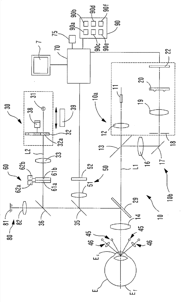
[0017] Next, the eye measurement device (this device) according to this embodiment will be described with reference to the drawings. figure 1 It is a brief structural diagram of the optical system and control system of the device. In addition, the lower optical system is housed in a box not shown in the figure. In addition, the box can be moved three-dimensionally with respect to the subject's eye E by a known movement mechanism for alignment. In addition, the box can also be hand-held (hand-held).

[0018] The measurement optical system 10 (optical system for objective...


PUM


Abstract

An eye measurement apparatus includes: a subjective measurement optical system configured to subjectively measure an examinee's eye, the subjective measurement optical system including: a chart to be presented to the examinee's eye; and a glare light source for irradiating the examinee's eye with a glare light; and a control part configured to determine presence or absence of opacity in a light transmitting part of the examinee's eye and, when the presence of opacity is determined, to allow display of necessity for a glare test which is a subjective measurement to be performed in a state that the examinee's eye is irradiated with the glare light.

Description

[0001] Cross References to Related Applications [0002] This application claims priority from Japanese Patent Application No. 2010-291187 filed with the Japan Patent Office on December 27, 2010, the entire contents of which are hereby incorporated by reference. technical field [0003] The present invention relates to an eye measuring device for measuring an eye to be inspected. Background technique [0004] There is known an apparatus (for example, an autorefractor) that objectively measures the refractive power of an eye to be inspected by irradiating a measurement beam to the fundus of the eye to be inspected and receiving reflected light of the measurement beam. [0005] In addition, Japanese Patent Laid-Open Publication No. Hei 7-16205 discloses an eye refractive power measuring device provided with an optical system for glare testing. [0006] The necessity of glare testing is judged by the inspector based on experience. However, inexperienced inspectors cannot easi...

Claims


Application Information

Patent Timeline
Patent Type & Authority Patents(China)
IPC IPC(8): A61B3/032A61B3/103A61B3/14
CPCA61B3/0008A61B3/036A61B3/032A61B3/103
Inventor 中村健二乡野光宏
Owner NIDEK CO LTD
Learn More